Self-calibration device and method for loop parameters of phase-locked loop

A technology of loop parameters and self-calibration, applied in automatic power control, electrical components, etc., can solve the problems of increasing chip area and cost, large chip area, and poor temperature compensation effect, so as to achieve good temperature compensation effect and overcome The effect of large chip area and small chip area

Active Publication Date: 2014-08-13
WUXI ZHONGKE MICROELECTRONICS IND TECH RES INST
View PDF5 Cites 16 Cited by
  • Summary
  • Abstract
  • Description
  • Claims
  • Application Information

AI Technical Summary

Problems solved by technology

The current process and technology allow the entire phase-locked loop to be integrated on the same chip. The output phase noise of the oscillator has a great relationship with the bandwidth of the filter. In order to obtain a lower phase noise, the bandwidth of the loop filter usually needs to be obtained Smaller, the resistance and capacitance values ​​in the loop filter are relatively large, which increases the area and cost of the chip; on the other hand, in the design of integrated circuits, a very important problem is process deviation, voltage fluctuation, ambient temperature (PVT ) and other factors will have a greater impact on circuit performance and consistency. Therefore, from a design point of view, it is necessary for the phase-locked loop circuit to have strong robustness and a correction circuit that suppresses the influence of factors such as PVT, because the larger resistance and capacitance It is more affected by factors such as temperature drift and process deviation, and the loop function gain and amplitude of the signal path show inconsistency. This problem needs to be solved from the design, and the existing public literature has made some attempts on the temperature compensation method. , but the effect is more limited
[0004] In the process of realizing the present invention, the inventors found that there are at least defects such as large chip area, high manufacturing cost and poor temperature compensation effect in the prior art

Method used


Image

  • Self-calibration device and method for loop parameters of phase-locked loop
  • Self-calibration device and method for loop parameters of phase-locked loop
  • Self-calibration device and method for loop parameters of phase-locked loop

Examples


Embodiment 1

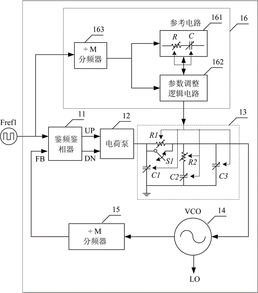
[0065] According to the sequence in the loop, the phase difference (frequency difference) between the reference clock signal and the frequency-divided output signal output by the VCO14 output through the variable frequency divider 15 is compared with the phase difference (frequency difference) between the two through the frequency detector and phase detector 11, and the pair loop of the charge pump 12 is determined. Whether the circuit filter 13 is charging or discharging, of course, this is also determined by the voltage-frequency characteristic curve of VCO14 (usually select the positive voltage-frequency characteristic curve, and the negative voltage-frequency characteristic curve is the opposite): if the frequency of the reference clock is higher than the frequency-divided output signal frequency, or the phase of the reference clock signal is ahead of the phase of the frequency division output signal, then the frequency detector 11 and the charge pump 12 work together to mak...

Embodiment 2

[0070] As shown in Figure 5(b), the RC reference circuit 161 includes an RC core module 1611'', a module 1612'' that provides a current source or voltage bias to the RC core module, and a module that supplies power to these two modules 1613'' (probably an LDO, or a DC-DC module). The core module RC core module 1611'' in this RC reference circuit 161. The RC core module 1611'' is a part of an RC oscillator. A typical implementation example of this RC oscillator is shown in Figure 5(b). By setting NMOS transistors with different width-to-length ratios, the Vgs of the two transistors The difference generates a reference current on the resistor R, which charges C through the mirror circuit, and the frequency of the output signal is closely related to the values ​​of R and C, and this oscillator may be a module in the entire transceiver, or It may be a separate module, which can be integrated in the IC of the entire transceiver.

[0071] The loop parameter calibration process is ...

Embodiment 3

[0074] As shown in FIG. 5(c), the RC reference circuit 161 includes an RC core module 1611''', a module 1612''' that provides a current source or voltage bias for the RC core module, and a module 1612''' for the two Module power supply module 1613''' (may be an LDO, or DC-DC module). The RC core module 1611''' is a part of an RC oscillator. The typical implementation example of this RC oscillator is shown in Figure 5(c). By setting NPN transistors of different areas, the difference of Vbe of the two transistors is A reference current is generated on the resistor R, and this current is charged to C by mirroring the mirror circuit, and the frequency of the output signal is closely related to the values ​​​​of R and C, and this oscillator may be a module in the entire transceiver, or it may It is a separate module that can be integrated in the IC of the entire transceiver. The loop parameter correction process is the same as that in Embodiment 2.

[0075] method embodiment ...


PUM


Abstract

The invention discloses a self-calibration device and method for the loop parameters of a phase-locked loop. The self-calibration device comprises a phase frequency detector, a charge pump, a loop filter, a loop parameter correcting module and a main frequency divider. The phase frequency detector, the charge pump and the loop filter are sequentially connected. The loop parameter correcting module shares a common reference signal Fref input end with the phase frequency detector, and is connected to the loop filter. The main frequency divider is connected with the output end of the loop filter and passes through the main frequency detector to be fed back and input to the feedback input end of the phase frequency detector. The self-calibration device and method for the loop parameters of the phase-locked loop can overcome the defects that in the prior art, the area of a chip is large, manufacturing cost is high, and a temperature compensation effect is bad are overcome, and achieve the advantages of being small in chip area, low in manufacturing cost and good in temperature compensation effect.

Description

technical field [0001] The invention relates to the technical field of semiconductor integrated circuits, in particular to a phase-locked loop loop parameter self-calibration device and method. Background technique [0002] With the rapid development of the personal consumer mobile terminal market, wireless communication technology has been widely used. In order to transmit information reliably and effectively, it is necessary to modulate the original data. In wireless communication technology, for the transmission of digital signals, in the transceiver or transmitter structure, the digital baseband processes the transmitted data, and the output through the baseband digital modulator The modulated signal performs amplitude, frequency or phase shift keying modulation on the RF carrier signal generated by the VCO or frequency divider. The modulated signal is output by the power amplifier and transmitted through the antenna to complete the wireless transmission of the digital s...

Claims


Application Information

Patent Timeline
Patent Type & Authority Applications(China)
IPC IPC(8): H03L7/18
Inventor 于云丰黄伟潘文光肖时茂
Owner WUXI ZHONGKE MICROELECTRONICS IND TECH RES INST
Why Eureka
Try Eureka