
Plasma heating decomposer

A thermal decomposer and plasma technology, applied in the direction of plasma, electrical components, etc., can solve the problems that electrodes are easily ablated, absorb a large amount of heat energy, and have a short service life, so as to overcome the easy ablation of electrodes and protect The effect of ecological environment and clean combustion

Active Publication Date: 2014-08-13
付顺坤
View PDF10 Cites 17 Cited by
  • Summary
  • Abstract
  • Description
  • Claims
  • Application Information

AI Technical Summary

Problems solved by technology

Existing plasma equipment cannot meet the requirements of harmful waste gas treatment or hydrogen production by pyrolyzing water, and the electrodes are easily ablated and have a short service life
[0004] The process of pyrolyzing water to produce hydrogen avoids the conversion process of "heat→work" and directly converts heat energy into hydrogen energy. The theoretical conversion efficiency is very high, but this reaction needs to absorb a large amount of heat energy

Method used


Image

  • Plasma heating decomposer
  • Plasma heating decomposer

Examples


Embodiment 1

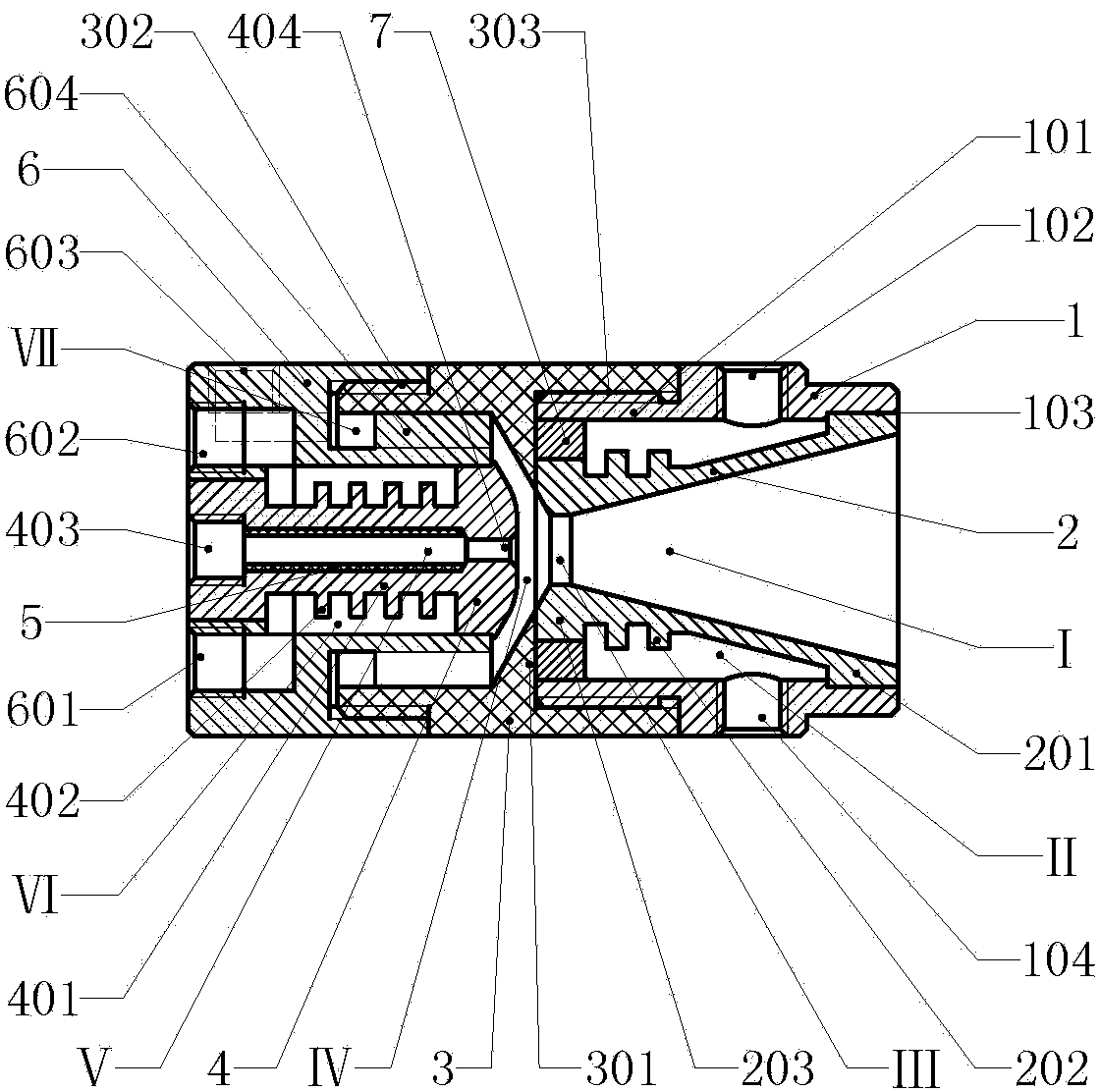
[0014] Example 1 figure 1In the shown embodiment, the plasma thermal decomposer is composed of anode casing (1), anode (2), cathode base (6), cathode (4) and insulating frame (3), wherein the anode casing (1) It is a circular sleeve structure, the front part of the anode sleeve (1) has a socket (103); the anode (2) is a trumpet-shaped rotary structure, and the anode (2) includes a front head (201), a trumpet-shaped wall and a rear The end (203), the trumpet-shaped inner space of the anode (2) constitutes a diffusion chamber (I), and the throat at the rear end of the diffusion chamber (I) constitutes a compression channel (Ⅲ), the compression channel (Ⅲ) is a circular straight hole, and the anode (2) Embedded in the anode sleeve (1), the front end (201) of the anode (2) is tightly assembled with the socket (103) at the front of the anode sleeve (1), and the outer wall of the anode (2) is connected to the anode sleeve ( There is a space between the inner walls of 1), and the sp...

Embodiment 2

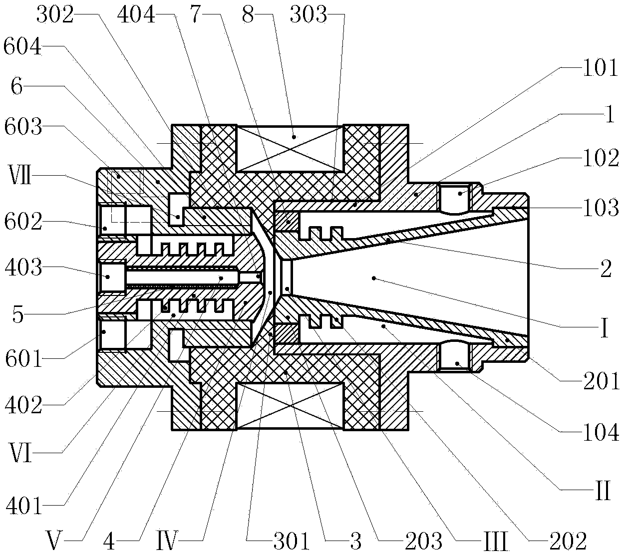
[0015] Example 2 figure 2 In the embodiment shown, the anode sleeve (1), insulating frame (3) and cathode base (6) are connected by means of flange connection, and the insulating frame (3) is used as a coil skeleton at the same time. 3) An electromagnetic coil (8) is arranged on the periphery. When working, the magnetic field generated by the electromagnetic coil (8) shrinks the ion arc inward to obtain a higher torch temperature. Other aspects are the same as those of the first embodiment, and will not be repeated here.

[0016] In the above embodiment, the anode cover (1) and the cathode base (6) are made of stainless steel, the anode (2) and the cathode (4) are made of red copper, and the insulating frame (3) is made of bakelite or polytetrafluoroethylene The material is made, and the thermal insulation bushing (5) is made of polytetrafluoroethylene material for use.

[0017] The above-mentioned embodiments are used as pyrolysis water hydrogen production equipment or as ...


PUM


Abstract

The invention relates to a plasma heating device, in particular to a plasma heating decomposer. The plasma heating decomposer is composed of an anode sleeve, an anode, a cathode substrate, a cathode and an insulating frame, wherein the anode is of a horn-shaped revolution solid structure, a diffusion cavity is formed in a horn-shaped inner space, a compression pore channel is formed by a throat at the rear end of the diffusion cavity, the anode is embedded into the anode sleeve, and a water jacket b is formed by the space between the outer wall of the anode and the anode sleeve; the cathode substrate is of a revolution solid structure with the center shaft protruding forwards, the cathode is embedded into the inner space of the center shaft of the cathode substrate, and a water jacket a is formed by space between the outer wall of a rod body of the cathode and the inner wall of the center shaft of the cathode substrate; the insulating frame is a connecting component between the anode sleeve and the cathode substrate, the anode sleeve is installed at the front end of the insulating frame, the cathode substrate is installed at the rear end of the insulating frame, a shrinking cavity is formed by the space between the front end of the center shaft of the cathode substrate and the compression pore channel at the rear end of the anode, and the head end of the cathode is arranged in the shrinking cavity. The plasma heating decomposer is suitable for production lines for hydrogen production through water pyrolysis or for treatment of hazardous substance and protects the ecological environment.

Description

technical field [0001] The present invention relates to plasma equipment, in particular to a plasma heating equipment. Background technique [0002] At present, plasma technology has been widely used, industrially used in plasma ignition, plasma spraying, metal smelting, plasma heating to manufacture nanomaterials, cutting, garbage incineration and waste treatment, etc. Plasma is a state formed under the ionosphere or discharge phenomenon. In the plasma generator, the discharge makes the gas molecules lose the outer electrons to form an ion state, which generates high temperature through mutual collision. Therefore, the plasma torch The temperature of the center of the torch can be as high as tens of thousands of degrees Celsius, and the temperature of the edge of the torch can also reach more than thousands of degrees. When the processed substance is impacted by the high-temperature plasma, its molecules will decompose, and the atoms will recombine to form new substances. ...

Claims


Application Information

Patent Timeline
Patent Type & Authority Applications(China)
IPC IPC(8): H05H1/34H05H1/42
Inventor 周开根
Owner 付顺坤
Learn More