Sludge drying system

A sludge drying and sludge drying technology, which is applied in the direction of temperature control sludge treatment, dewatering/drying/concentrating sludge treatment, etc. Increase and other problems to achieve the effect of improving the utilization rate of heat energy, increasing the contact area, and increasing the drying speed of the block

Active Publication Date: 2014-08-20
GUANGZHOU HISEN ENVIRONMENTAL PROTECTION CO LTD
View PDF9 Cites 11 Cited by
  • Summary
  • Abstract
  • Description
  • Claims
  • Application Information

AI Technical Summary

Problems solved by technology

This drying method has the following problems: (1) heat energy cannot be recycled, and heat energy is seriously wasted; (2) exhaust gas emissions are large, increasing secondary pollution
[0006] Other indirect heat drying methods generally have the following problems: (1) The existing indirect drying equipment adopts a single-channel design, which is bulky and occupies a large area; (2) The degree of wet sludge reduction in the drying process is relatively low. Large, the tail section of the single-channel dryer often has a sharp decrease in sludge volume, and the proportion of hot air in the tail section increases
Because the water vapor in the cylinder needs to be pumped out for treatment in a slightly negative pressure environment, the excess hot air taken away at the end leads to waste of heat energy, and the utilization rate of heat energy is low; (3) During the sludge drying process, single-channel design During the drying process, the water vapor concentration in each part of the cylinder does not change much, resulting in low sludge drying efficiency; (4) The design of a single oil circuit (heat carrier heat transfer oil) is adopted, and the oil temperature cannot be adjusted during the drying process, which affects the thermal energy. Best utilization effect; (5) Most dryers cannot recycle heat medium

Method used


Image

  • Sludge drying system
  • Sludge drying system
  • Sludge drying system

Examples


Embodiment Construction

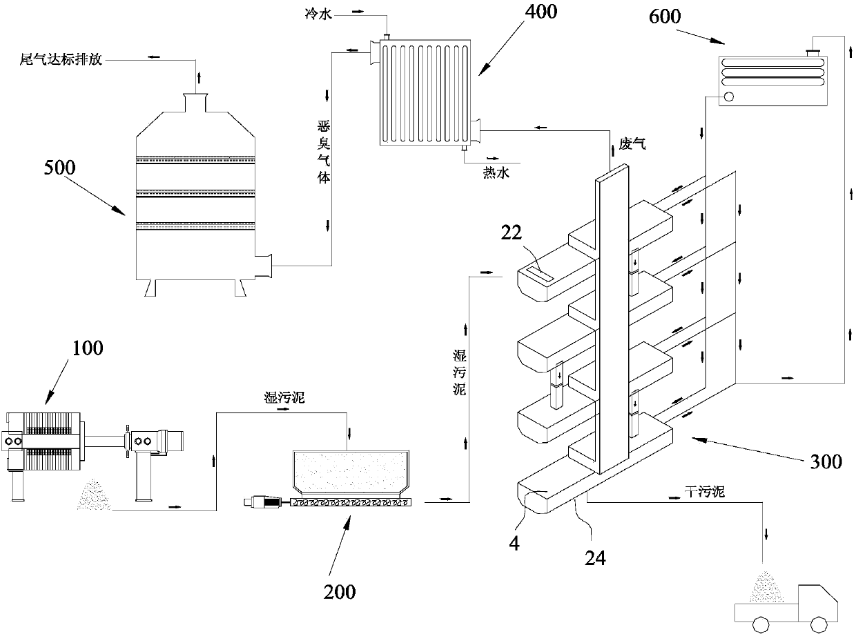
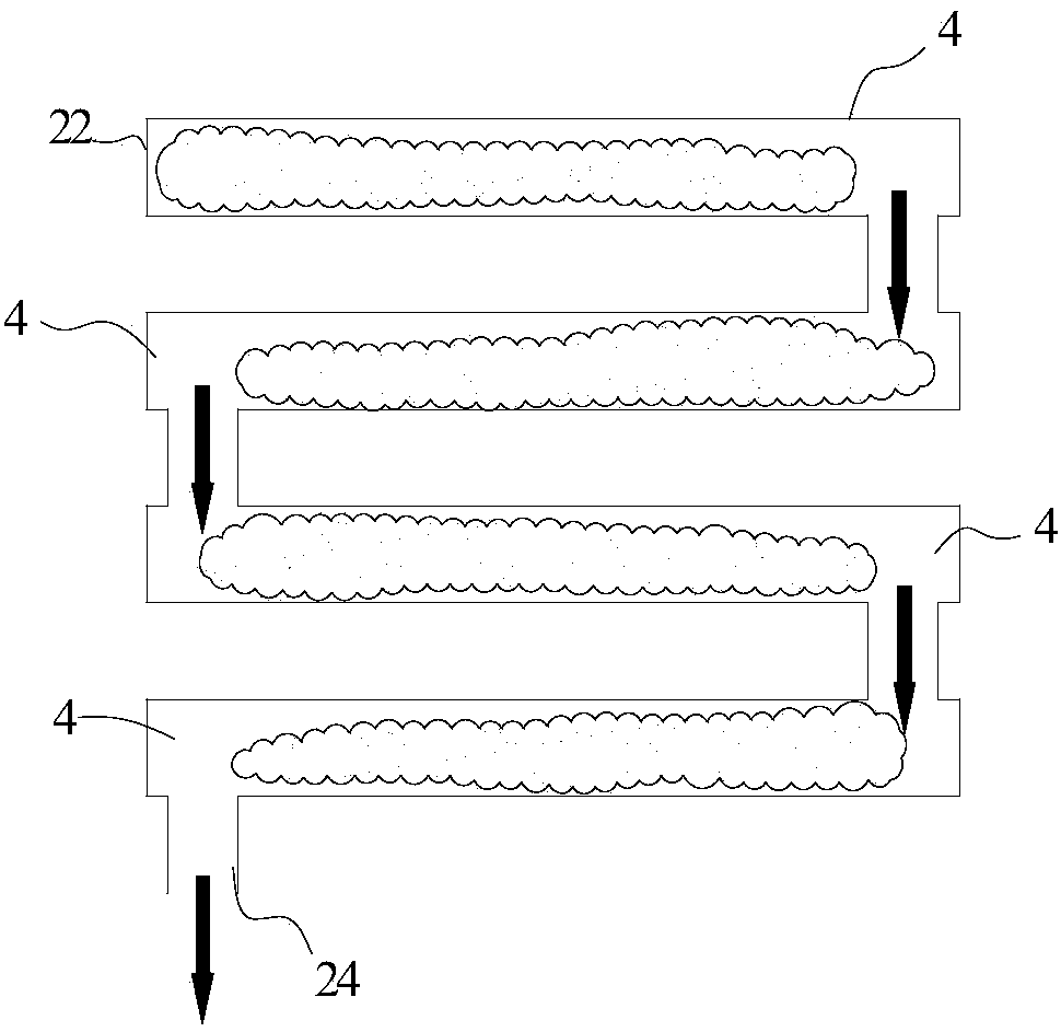
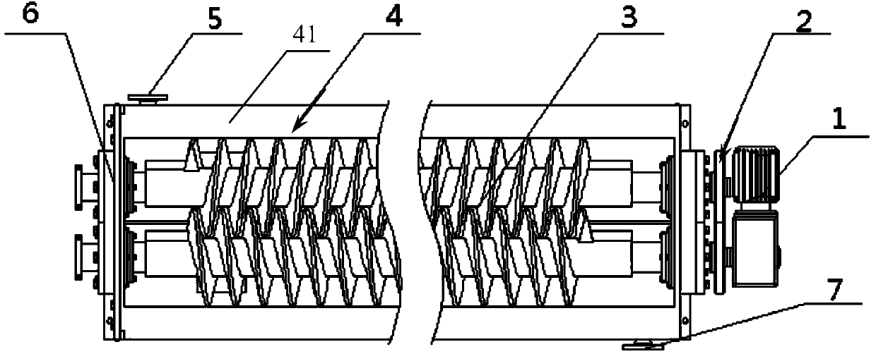
[0040] Such as Figure 1~2 A sludge drying system shown includes a filter press 100 for sludge dehydration, a sludge storage hopper 200 for sludge storage, a sludge dryer 300 for heating and drying sludge, and a sludge dryer 300 for sludge dehydration. The steam condenser 400 for recovering the heat energy of the waste gas, the deodorization tower 500 for deodorizing the waste gas and the heat conduction oil furnace 600 for heating the hot oil, the outlet of the filter press 100 is connected with the inlet of the mud storage hopper 200, and the mud storage The outlet of the bucket 200 is connected to the feed end of the sludge dryer 300. The sludge dryer 300 includes at least two layers of drying boxes 4 stacked from top to bottom and drying devices respectively located in the drying boxes 4. Each drying box 4 Each has an input port 22 for feeding in sludge, a discharge port 24 for outputting sludge, and an exhaust port 23 for exhausting exhaust gas. Each drying device has an ...


PUM


Abstract

The invention discloses a sludge drying system, which comprises a filter press, a sludge storage hopper, a sludge dryer, a steam condenser, a deodorization tower and a hot oil furnace, wherein the sludge dryer comprises at least two layers of drying cabinets which are laminated from top to bottom, and drying devices respectively positioned in the drying cabinets, each drying cabinet is provided with a feeding end, a discharging end and an exhaust end, each drying device is provided with an oil inlet for leading hot oil to the drying device, and an oil outlet for outputting the hot oil; the drying cabinets are connected through the feeding ends and the discharging ends, and are connected in series and communicated by taking connecting points as serial points; and the exhaust ends are connected in series and then are connected with a gas inlet of the steam condenser, a gas outlet of the steam condenser is connected with a gas inlet of the deodorization tower, each oil inlet is gathered and connected to an oil outlet end of the hot oil furnace, each oil outlet is gathered and connected to an oil inlet end of the hot oil furnace. The sludge drying system can recycle hot oil, and can also recycle exhausted hot waste gas, and promotes heat utilization rate and sludge drying efficiency.

Description

[0001] technical field [0002] The invention relates to drying technology, in particular to a sludge drying system. Background technique [0003] At present, the urban sludge brought by industrial wastewater discharge has gradually become a serious environmental problem. However, the processing speed of domestic sewage treatment plants is far behind the output of sewage, causing environmental pollution. [0004] The existing sewage treatment method is to dry the sludge in the sewage, generally including direct thermal drying and indirect thermal drying. in: [0005] Direct heat drying is the application of thermal convection drying technology. After heating, the heat medium enters the drying machine and directly contacts and mixes with the sludge. The sludge heats up and the water evaporates. During this process, the thermal medium is polluted by direct contact with the sludge, and the discharged waste steam and waste water must be discharged after harmless treatment. T...

Claims


Application Information

Patent Timeline
Patent Type & Authority Applications(China)
IPC IPC(8): C02F11/12C02F11/18
Inventor 顾玉民王弘
Owner GUANGZHOU HISEN ENVIRONMENTAL PROTECTION CO LTD
Why Eureka
Try Eureka