
Vacuum evaporation coating method and rare earth magnet covered with evaporation coating

A technology of vacuum evaporation and rare earth magnets, which is applied in the field of magnet manufacturing, can solve the problems of excessive oxidation, poor protection effect, peeling, etc., and achieve the effects of preventing excessive oxidation, overcoming oxidative damage, and overcoming weak binding force

Active Publication Date: 2014-09-10
FUJIAN CHANGJIANG GOLDEN DRAGON RARE EARTH CO LTD
View PDF4 Cites 5 Cited by
  • Summary
  • Abstract
  • Description
  • Claims
  • Application Information

AI Technical Summary

Problems solved by technology

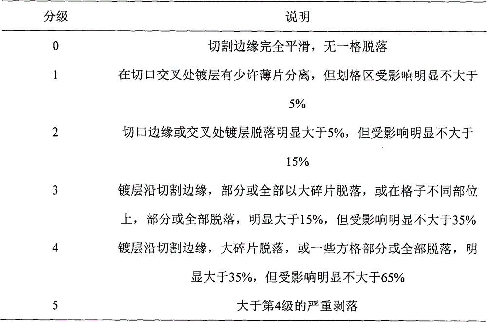
However, for the rare earth magnet metal coatings prepared in the existing way, the binding force between Mg, Al, Zn coatings and the surface of rare earth magnets is much lower than that of MgO, Al 2 o 3 , The binding force between ZnO and the surface of the rare earth magnet, it is easy to peel off from the surface of the magnet, and the protection effect is not good
[0004] At present, the use of MgO vacuum evaporation coating as a protective medium layer has been widely used on glass and silicon wafers. When MgO coating is performed, MgO is generally used as a target, and electron beams or lasers are used to focus the surface of the MgO target to melt the MgO. is evaporated, but the cost is too high
In order to solve this problem, the invention patent CN1156600C adopts the S-gun magnetron sputtering method, using conical pure magnesium as the target, Ar gas as the protective gas, and oxygen as the reactive gas to obtain a dense and compact material with a thickness of about 0.5-1.2 μm. Uniform MgO functional film, but this coating method uses a large amount of oxygen, which is easy to cause excessive oxidation for rare earth magnets and seriously affects product performance, so it is not suitable for rare earth magnet coating

Method used


Image

  • Vacuum evaporation coating method and rare earth magnet covered with evaporation coating
  • Vacuum evaporation coating method and rare earth magnet covered with evaporation coating
  • Vacuum evaporation coating method and rare earth magnet covered with evaporation coating

Examples


Embodiment 1

[0052] A rare earth magnet sintered body was prepared, the sintered body had the following atomic composition: Dy was 5, Lu was 0.2, Er was 0.2, Nd was 8.5, Tm was 0.5, Y was 0.1, Co was 1, C was 0.05, and B was 7 , Cu is 0.2, Mn is 0.2, Ga is 0.2, Bi is 0.1, Ti is 0.3, and Fe is the balance. It is produced according to the existing procedures of smelting, flake flakes, hydrogen crushing, jet milling, pressing, sintering and heat treatment of rare earth magnets.

[0053] The heat-treated sintered body is processed into a magnet of 30mm×30mm×5mm, and the direction of 5mm is the orientation direction of the magnetic field. Set of magnets (10 pieces).

[0054] Take another group of magnets (10 pieces) with clean surface as a blank example.

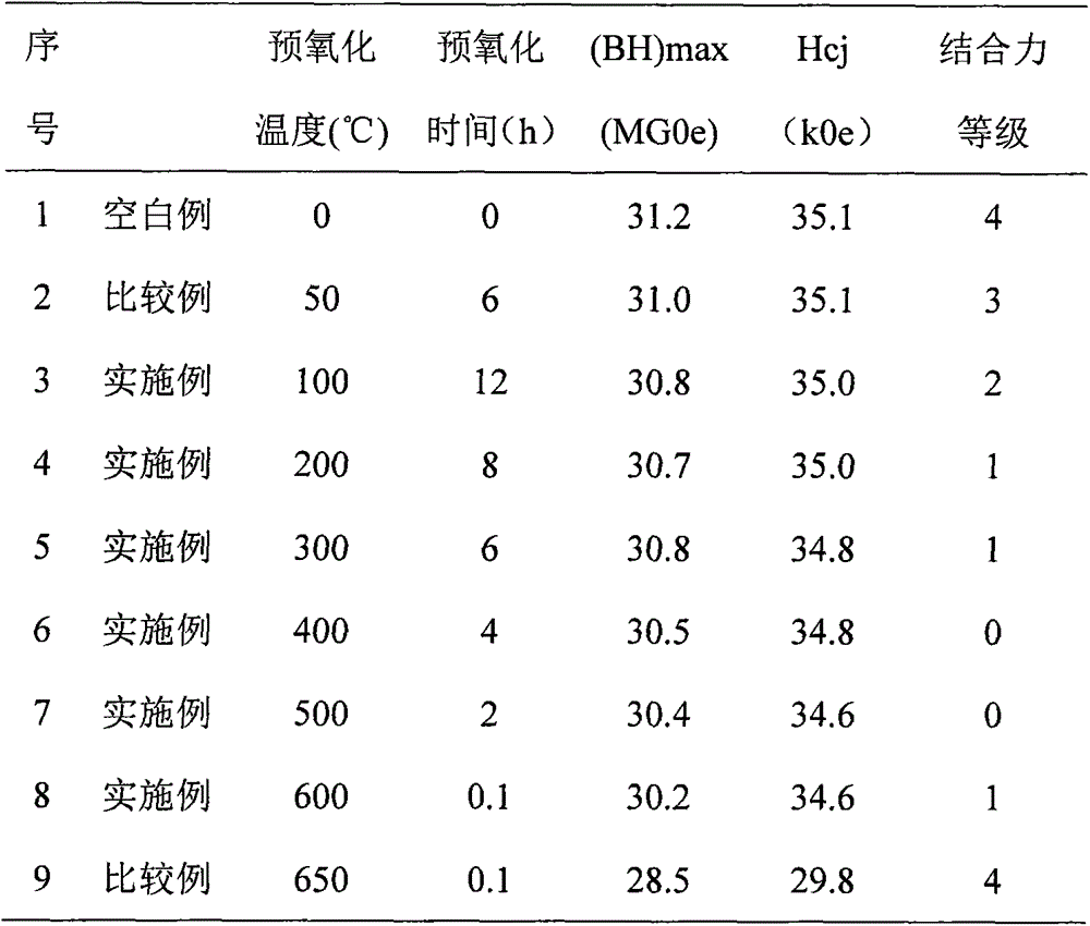
[0055] Send the workpiece racks fixed with magnets into different coating chambers, and move to each coating chamber at a distance of 0.5m 3 Oxygen is introduced at a rate of / hr, and heated to 50-650°C respectively, and pre-oxidized for 0...

Embodiment 2

[0068] A rare earth magnet sintered body was prepared, the sintered body had the following atomic composition: Dy was 5, Lu was 0.2, Er was 0.2, Nd was 8.5, Tm was 0.5, Y was 0.1, Co was 1, C was 0.05, and B was 7 , Cu is 0.2, Mn is 0.2, Ga is 0.2, Bi is 0.1, Ti is 0.3, and Fe is the balance. It is produced according to the existing procedures of smelting, flake flakes, hydrogen crushing, jet milling, pressing, sintering and heat treatment of rare earth magnets.

[0069] The heat-treated sintered body is processed into a 30mm×30mm×8mm magnet, and the 8mm direction is the orientation direction of the magnetic field. After the processed magnet is sandblasted, purged, and cleaned, the surface is finally installed on the workpiece frame, and installed on each workpiece frame. A set of magnets (10 pieces).

[0070] Take another group of magnets (10 pieces) with clean surface as a blank example.

[0071] Send the workpiece racks fixed with magnets into different coating chambers, ...

Embodiment 3

[0082] A rare earth magnet sintered body was prepared, the sintered body had the following atomic composition: Dy was 5, Lu was 0.2, Er was 0.2, Nd was 8.5, Tm was 0.5, Y was 0.1, Co was 1, C was 0.05, and B was 7 , Cu is 0.2, Mn is 0.2, Ga is 0.2, Bi is 0.1, Ti is 0.3, and Fe is the balance. It is produced according to the existing procedures of smelting, flake flakes, hydrogen crushing, jet milling, pressing, sintering and heat treatment of rare earth magnets.

[0083] The heat-treated sintered body is processed into a 30mm×30mm×8mm magnet, and the 8mm direction is the orientation direction of the magnetic field. After the processed magnet is sandblasted, purged, and the surface is cleaned, it is then installed on the workpiece holder, and 10 pieces are installed on the workpiece holder. magnet.

[0084] Send the workpiece frame fixed with the magnet into the coating chamber, and move 1.0m away from the coating chamber. 3 Oxygen is fed at a rate of / hr, and heated to 200°C...


PUM


Abstract

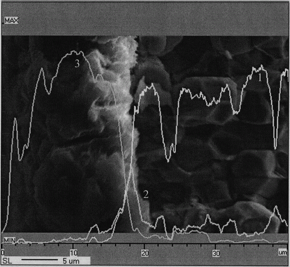
The invention discloses a vacuum evaporation coating method and a rare earth magnet covered with an evaporation coating. The method includes steps of: 1) installing a rare earth magnet workpiece to a workpiece rest before pretreatment; 2) sending the workpiece rest into a reaction chamber, and performing preoxidation; 3) sending the workpiece rest to a coating chamber, vacuumizing, heating a meta evaporating material M to an evaporation temperature, and subjecting the rare earth magnet workpiece to evaporation coating; and 4) cooling, restoring to normal pressure and taking the workpiece out. According to the method, the rare earth magnet is subjected to trace oxidation in advance and is subjected to replacement by feeding M steam, thus preventing excessive oxidation of the rare earth magnet, and obtaining a dense MO distribution thin layer and an M layer firmly connected to the MO distribution thin layer.

Description

technical field [0001] The invention relates to the technical field of magnet manufacture, in particular to a method for vacuum evaporation coating and a rare earth magnet covered with evaporation coating. Background technique [0002] Since rare earth magnets are prone to rust, the surface needs to be protected by coating during production. However, the traditional electroplating method has great limitations. Not only is it difficult to control the thickness of the coating, but the surface of the coating is prone to defects such as pitting, hard thorns, peeling, burnt, spots, shadows, and build-up, which will shorten the life of NdFe The service life of boron magnets, while the wastewater generated by electroplating needs secondary treatment to meet the discharge standards, which not only increases production costs, but is also harmful to the environment. [0003] The above-mentioned defects can be avoided by using vacuum evaporation coating technology, and the coating pri...

Claims


Application Information

Patent Timeline
IPC IPC(8): C23C14/24C23C14/18H01F41/20
Inventor 永田浩傅东辉翁松青
Owner FUJIAN CHANGJIANG GOLDEN DRAGON RARE EARTH CO LTD
Learn More