

Organic light emitting device and preparation method thereof
An electroluminescent device and electroluminescent technology, which can be applied in the fields of electro-solid devices, semiconductor/solid-state device manufacturing, electrical components, etc., and can solve problems such as low luminous efficiency
- Summary
- Abstract
- Description
- Claims
- Application Information
AI Technical Summary
Problems solved by technology
Method used
Image

Examples
preparation example Construction
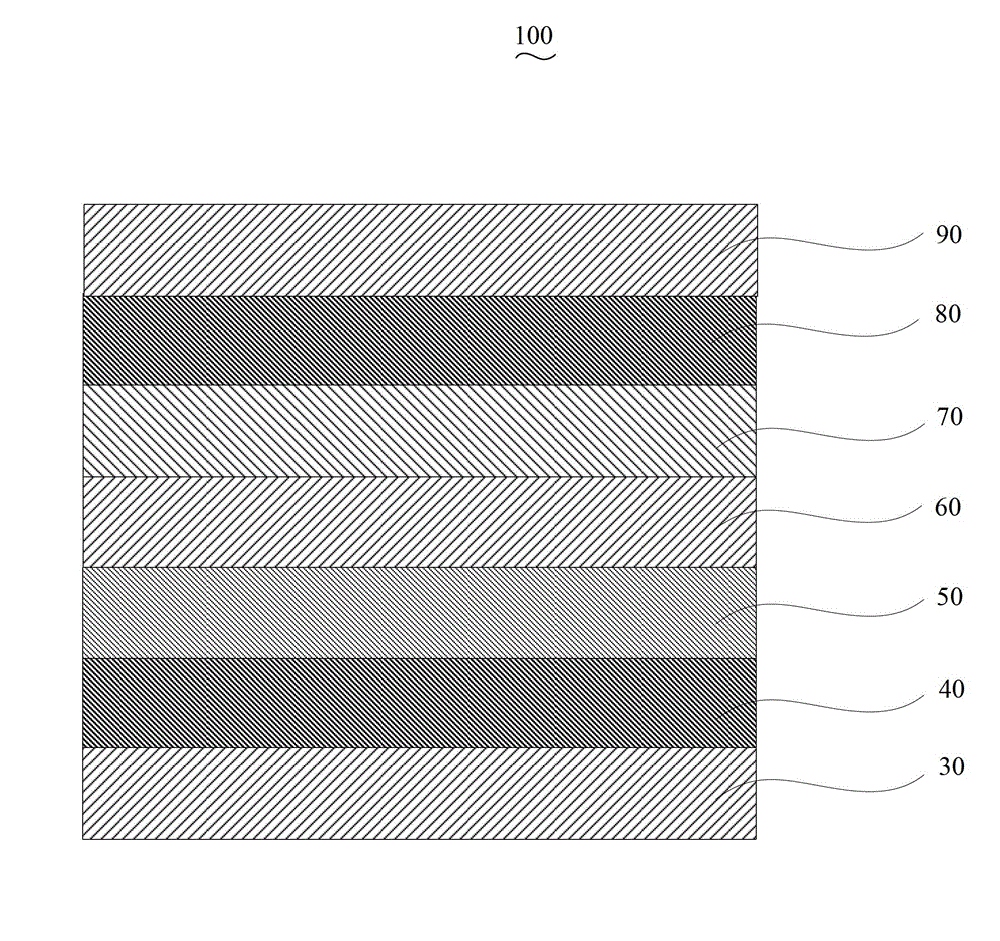
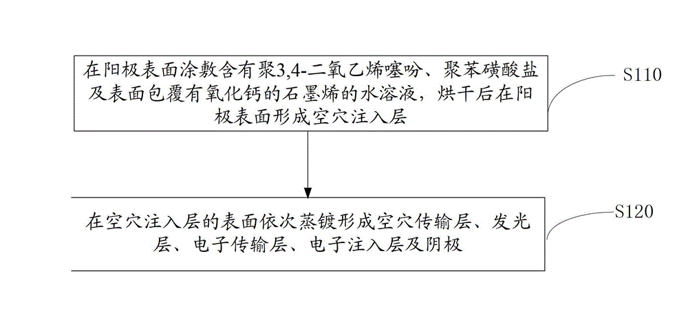
[0031] Please also see figure 2 , the preparation method of the organic electroluminescent device 100 of an embodiment, it comprises the following steps:
[0032] Step S110, coating an aqueous solution containing poly-3,4-dioxyethylenethiophene, polybenzenesulfonate, and graphene coated with calcium oxide on the surface of the anode 30, and forming a hole injection layer on the surface of the anode 30 after drying 40.
[0033] The material of the anode 30 is indium tin oxide glass (ITO), aluminum zinc oxide glass (AZO) or indium zinc oxide glass (IZO), preferably ITO.
[0034] In this embodiment, before the hole injection layer 40 is formed on the surface of the anode 30, photolithography treatment is carried out, and the size is cut into the required size, and then ultrasonicated for 15 minutes with detergent, deionized water, acetone, ethanol, and isopropanol. Remove organic pollutants from glass surfaces.
[0035] In this embodiment, the hole injection layer has a thick...
Embodiment 1
[0049] In this example, an organic electroluminescent device with a structure of ITO glass / calcium oxide graphene: PEDOT:PSS / NPB / ADN / TAZ / CsF / Ag was prepared.
[0050] Firstly, the ITO glass substrate was washed with detergent, deionized water, and ultrasonic for 15 minutes to remove organic pollutants on the glass surface; the surface of the ITO glass substrate was spin-coated with PEDOT, PSS and graphene coated with calcium oxide on the surface (in this paper Indicates coating, such as calcium oxide graphene indicates graphene coated with calcium oxide on the surface; ":" indicates a mixture, calcium oxide graphene: PEDOT:PSS indicates a mixture of PEDOT, PSS and graphene coated with calcium oxide on the surface ) aqueous solution to prepare the hole injection layer, the mass ratio of PEDOT and PSS is 4:1, the mass ratio of PEDOT and water is 3.5:100, and the mass ratio of graphene coated with calcium oxide on the surface and PEDOT is 1:20, The mass ratio of calcium oxide to ...
Embodiment 2
[0055] The structure prepared in this example is AZO glass / calcium oxide graphene: PEDOT:PSS / TCTA / Alq 3 / Bphen / Cs 2 CO 3 / Al organic electroluminescent devices.
[0056] First, the AZO glass substrate is sequentially washed with detergent, deionized water, and ultrasonic for 15 minutes to remove organic pollutants on the glass surface; the surface of the AZO glass substrate is spin-coated with an aqueous solution containing PEDOT, PSS, and graphene coated with calcium oxide on the surface. Hole injection layer, the mass ratio of PEDOT and PSS is 2:1, the mass ratio of PEDOT and water is 1:100, the mass ratio of graphene coated with calcium oxide on the surface and PEDOT is 1:100, the mass ratio of calcium oxide and graphite The mass ratio of alkene is 1:5, wherein the graphene coated with calcium oxide on the surface has the following steps to prepare, the calcium chloride solution with a mass concentration of 30% is mixed with graphene, the quality of graphene and calcium c...
PUM
 Abstract
Description
Claims
Application Information