Continuous coating production system of sheet substrates

A production system and technology for substrates, which are applied in sputtering coating, ion implantation coating, vacuum evaporation coating and other directions, can solve the problems of stress loss of tempered glass base, unattainable and decreased strength of thermochromic smart glass, etc. To achieve the effect of reducing stress loss

Active Publication Date: 2014-09-24
GUANGZHOU INST OF ENERGY CONVERSION - CHINESE ACAD OF SCI
View PDF7 Cites 19 Cited by
  • Summary
  • Abstract
  • Description
  • Claims
  • Application Information

AI Technical Summary

Problems solved by technology

Therefore, it is necessary to choose tempered glass with better temperature resistance as the substrate. However, the stress loss of tempered glass has already begun to appear in the temperature range of 400 ° C to 600 ° C, resulting in a decrease in safety performance. The longer the temperature condition is maintained, the greater the stress loss. , and eventually the strength of the prepared thermochromic smart glass cannot meet the relevant national or industry standards for use, so the development of relevant process routes and production equipment needs to consider this important issue
[0003] Chinese patent CN103204636A discloses a heating and cooling system for transparent conductive oxide-coated glass coating line. This equipment can be used for the process route of depositing thermochromatic coating materials at one time under high temperature conditions. However, the structure is complicated and inconvenient to maintain, and a resistive heating method is adopted. The efficiency is low. In order to maintain the temperature required for the deposited film, both the upper and lower surfaces of the glass are heated. The glass as a whole is in a high temperature state of 400°C to 600°C required for the deposition of thermochromic coating materials, which will inevitably lead to a decrease in the stress loss safety performance of the tempered glass base. , can not meet the relevant national or industry standards, such as GB15763.2-2005 safety glass for construction - tempered glass, GB17841-1999 tempered glass and semi-tempered glass for curtain walls, and GB18045-2000 safety glass for railway vehicles
In addition, the overall glass absorbs more heat and cools down slowly, which is not conducive to rapid cooling to improve the stress loss of tempered glass, and the heating and cooling processes consume a lot of energy.
Chinese patent CN101008074A provides an infrared heating device with a rotating reflector and a coating device that can realize substrate rotation and movement, but its complex structure is not conducive to the large-scale thermochromic smart glass in the equipment structure shown in the figure. Frequent movement on the platform, in addition, the heating system is located inside the vacuum chamber as a whole, the service life is seriously affected due to heat dissipation and other reasons, and the maintenance of the infrared radiation lamp is not convenient
Chinese patent CN2846440Y proposes a heater for a continuous coating device, and an insulating layer is set in the vacuum chamber. As a result, the treated substrate is heated by the non-primary surface layer of the film layer due to the secondary radiation of the environment, but the overall temperature of the substrate. If the annealing treatment applied to the glass-based thermochromic coating material will obviously affect the tempering stress loss, and at the same time, the cooling rate will decrease due to more glass absorption
In addition, the radiation tube is completely placed in the vacuum chamber, which seriously affects the service life due to heat dissipation and other reasons, and the maintenance of the infrared radiation tube is also inconvenient

Method used


Image

  • Continuous coating production system of sheet substrates
  • Continuous coating production system of sheet substrates
  • Continuous coating production system of sheet substrates

Examples


Embodiment 1

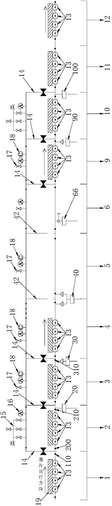
[0054] Taking tempered glass-based thermochromatic intelligent glass coating production as an example, such as figure 1 The continuous coating system shown includes a film feeding platform 1 , a working area and an unloading platform 12 . The working area is equipped with various functional rooms for coating and annealing operations, including the first coating deposition room 5, the rapid atmosphere annealing room 6 and the air grid quenching area 11. Five vacuum chambers are also installed in the working area, namely the first vacuum chamber 2 , the second vacuum chamber 3 , the first transition chamber 4 , the third vacuum chamber 9 and the fourth vacuum chamber 10 . Each functional room is according to the film feeding table 1-first vacuum chamber 2-second vacuum chamber 3-first transition chamber 4-coating deposition chamber 5-rapid atmosphere annealing chamber 6-third vacuum chamber 9-fourth vacuum chamber 10- The sequence of air grid quenching zone 11-unloading platfor...

Embodiment 2

[0082] The difference between this embodiment 2 and embodiment 1 is that, in addition to a first coating deposition chamber 5 connected upstream of the rapid atmosphere annealing chamber 6, a second coating deposition chamber 7 is also connected downstream of the rapid atmosphere annealing chamber 6 . A second transition chamber 8 is connected downstream of the second coating deposition chamber 7 . The second coating deposition chamber 7 and the second transition chamber 8 are connected with a fifth vacuum pump group 78 . After the substrate is removed from the rapid atmosphere annealing chamber 6, it will enter the second coating deposition chamber 7 located downstream of the rapid atmosphere annealing chamber 6 for the second coating treatment, thereby depositing a multilayer composite film on the upper surface of the glass substrate. The glass substrate that moves out from the second coating deposition chamber 7 subsequently enters the second transition chamber 8 positione...


PUM


Abstract

The invention discloses a continuous coating production system of sheet substrates. The continuous coating production system comprises a feeding area, a working area and a discharge area, all of which are orderly communicated with each other; the feeding area comprises a sheet feeding table; the working area comprises a plurality of pre-vacuumizing chambers, a first transition chamber, a coating deposition chamber, a quick atmosphere annealing chamber and a plurality of pre-vacuumizing chambers orderly in the coating process flow direction; the discharge area comprises a discharge table; each chamber of the working area is provided with the desired vacuum environment. The continuous coating production system further comprises a transporting device capable of realizing linear transmission; the transporting device penetrates through the whole feeding area, the working area and the discharge area. The continuous coating system has the advantages that the regional continuous film deposition and annealing of a one-layer or multi-layer composite film containing a hot color coating material in the same production line are realized, the production efficiency is obviously improved, and meanwhile, the material loss cost of the material in the off-line annealing process after coating is reduced. Due to unique structural design of the system, the problem of tempering stress loss can be obviously solved; the stress of the tempered glass based smart glass produced by the system is up to the stress standard of the national building energy-saving safety glass, namely greater than or equal to 90Mpa.

Description

technical field [0001] The invention relates to the field of production and preparation of thermochromic coating materials, in particular to a continuous coating production system for sheet substrates. Background technique [0002] Due to the pressure of energy shortage, countries all over the world are paying great attention to the field of building energy conservation, which accounts for one-third of the total energy consumption of the society, especially the energy conservation of building doors and windows has become the focus of attention. For this reason, LOW-E energy-saving door and window glass has been widely used, but the optical properties cannot be changed with people's will or environmental conditions, and its comfort and energy-saving effects have limitations. In contrast, thermochromic coating materials (especially thermochromic smart glass) have the function of controlling heat gain with changes in ambient temperature, and their energy-saving effect is more o...

Claims


Application Information

Patent Timeline
Patent Type & Authority Applications(China)
IPC IPC(8): C23C14/56C23C14/34C23C14/58
Inventor 徐刚詹勇军熊斌黄华凛孙耀明
Owner GUANGZHOU INST OF ENERGY CONVERSION - CHINESE ACAD OF SCI
Why Eureka
Try Eureka