Automobile gasoline carburetor and operation method thereof
A gasifier and gasoline technology, applied in chemical instruments and methods, carburetors, exhaust devices, etc., can solve problems such as difficult application of gasification systems and complex engine systems, and achieve excellent heat transfer performance, good synergy, The effect of increasing strength
- Summary
- Abstract
- Description
- Claims
- Application Information
AI Technical Summary
Problems solved by technology
Method used
Image

Examples
Embodiment 1
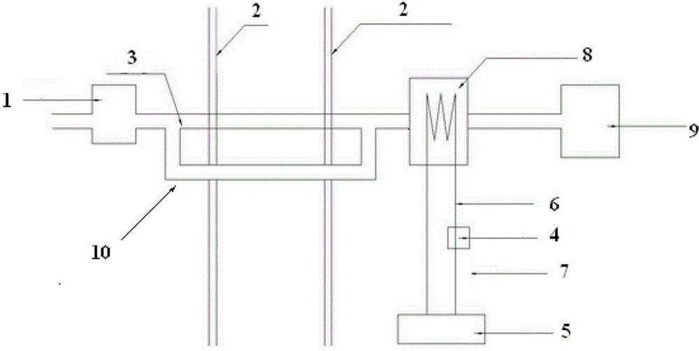
[0041] A kind of gasoline vaporizer, this gasoline vaporizer comprises: oil delivery pipe 3, oil delivery branch pipe 10, exhaust pipe 2, electric furnace wire 8, insulating layer 7, electric wire 6 and accumulator 5; Wherein, the entrance of oil delivery copper pipe 3 It is connected with the oil delivery port of the oil delivery pump 1, and the outlet of the oil delivery pipe 3 is connected with the input port of the carburetor 9; the front end of the oil delivery pipe 3 has two through holes on the same side wall, and the two ends of the oil delivery branch pipe 10 are respectively welded on the two In a through hole, the oil delivery branch pipe and the oil delivery copper pipe form a square shape, and the automobile exhaust pipe 2 passes through the mouth shape, and is in close contact with the oil delivery copper pipe 3 and the oil delivery branch pipe 10. The storage battery 5, the switch 4 and the electric furnace wire 8 form a circuit through the electric wire 6, and t...
Embodiment 2
[0043] The copper alloy for manufacturing the oil delivery pipe and the oil delivery branch pipe described in Example 1 comprises: based on the total weight of the copper alloy, 2.0% by mass of Mn, 2.5% by mass of Fe, 0.3% by mass of Ni, 0.3% by mass of silicon, 0.01% by mass of P, the balance being Cu and unavoidable impurities. According to the conventional pipe processing method, a copper pipe with a diameter of 5mm and a wall thickness of 0.5mm is made from this alloy. According to the standard measurement method in GB (National Standard), the thermal conductivity of the copper pipe is measured to be 480W / m-°C , The tensile strength is 320MPa.
Embodiment 3
[0048] From the copper alloy in Example 2, copper pipes for oil pipelines and oil pipelines are made according to conventional pipe processing methods, and the copper pipes are processed as follows: (1) tempering treatment, (2) cryogenic treatment, step (3) ) tempering treatment again, and step (4) cryogenic treatment again, wherein the tempering treatment in step (1) is low temperature tempering, the treatment temperature is 100°C, the treatment time is 4h, and the cryogenic treatment temperature in step (2) is about -70°C, the treatment time is 4h, the tempering treatment in step (3) is high temperature tempering, the treatment temperature is 600°C, the treatment time is 4h, the cryogenic treatment temperature in step (4) is about -200°C, and the treatment time is 1h, after the cryogenic treatment in step (2), control the temperature of the copper tube back to room temperature with a heating rate of 8°C / min. After the cryogenic treatment in step (4), control the temperature o...
PUM
| Property | Measurement | Unit |
|---|---|---|
| specific surface area | aaaaa | aaaaa |
| particle size | aaaaa | aaaaa |
| diameter | aaaaa | aaaaa |
Abstract
Description
Claims
Application Information
 - R&D
- Intellectual Property
- Life Sciences
- Materials
- Tech Scout
- Unparalleled Data Quality
- Higher Quality Content
- 60% Fewer Hallucinations
Browse by: Latest US Patents, China's latest patents, Technical Efficacy Thesaurus, Application Domain, Technology Topic, Popular Technical Reports.
© 2025 PatSnap. All rights reserved.Legal|Privacy policy|Modern Slavery Act Transparency Statement|Sitemap|About US| Contact US: help@patsnap.com