Preparation method and application of TiO2 buffer layer not subjected to annealing treatment

A technology of annealing treatment and buffer layer

Active Publication Date: 2014-10-15
CENT SOUTH UNIV
View PDF5 Cites 5 Cited by
  • Summary
  • Abstract
  • Description
  • Claims
  • Application Information

AI Technical Summary

Problems solved by technology

However, due to its crystalline surface linking many TiO x , leading to low efficiency without annealing

Method used


Image

  • Preparation method and application of TiO2 buffer layer not subjected to annealing treatment
  • Preparation method and application of TiO2 buffer layer not subjected to annealing treatment
  • Preparation method and application of TiO2 buffer layer not subjected to annealing treatment

Examples


Embodiment 1

[0054] TiO of the present invention 2 Specific examples of NPs synthesis and improving the efficiency and stability of OPV devices, the specific steps are as follows:

[0055] 1) Mix 50mL of n-butanol and 1.6mL of nitric acid in a wide-mouth Erlenmeyer flask, stir thoroughly for 10 minutes, and add 5mL of acetic acid at the same time, and wait until the mixture is uniform. At this time, the pH of the system is 0.2, and the system is heated to 40°C;

[0056] 2) Slowly add 24mL tetrabutyl titanate dropwise to the above solution, and stir at 40°C for 40min;

[0057] 3) Add 8 mL of deionized water dropwise to the solution in B at a rate of 0.02 mL / S. After it is completely hydrolyzed to form a gel, add 100 mL of deionized water and continue stirring at 40°C for 24 hours to obtain a transparent sol;

[0058] 4) After standing for 24 hours, stop stirring, and use a separatory funnel to separate n-butanol;

[0059] 5) Heat the sol to 80°C for 60 minutes, then react at 150°C for 30 ...

Embodiment 2

[0075] 1) Mix 20mL of n-butanol and 0.1mL of nitric acid in a wide-mouth conical flask, stir thoroughly for 10 minutes, and add 2mL of acetic acid at the same time, and wait until the mixture is uniform. At this time, the pH of the system is 1, and the system is heated to 30°C;

[0076] 2) Slowly add 10 mL of tetrabutyl titanate dropwise to the above solution, and stir at 30°C for 30 min;

[0077] 3) Add 3 mL of deionized water dropwise to the solution in B at a rate of 0.002 mL / S, add 100 mL of isopropanol after it is hydrolyzed to form a gel, and continue stirring at 40°C for 4 hours to obtain a transparent sol;

[0078] 4) Heat the sol to 70°C for 90 minutes, then react at 160°C for 30 minutes, then cool down to 80°C for 60 minutes, then heat up to 150°C for 30 minutes; repeat three times to obtain highly dispersed TiO 2 Nanocrystalline sol;

[0079] 5) Finally, the above-mentioned high-dispersion TiO 2 The nanocrystalline sol was diluted with alcohol 10 times the volume ...

Embodiment 3

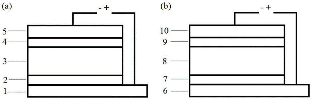
[0085] 1) The commercially purchased ITO was ultrasonically cleaned in acetone, detergent, deionized water, and isopropanol, dried with nitrogen after cleaning, treated with ozone for 10 minutes, and placed in a Petri dish for use as a cathode;

[0086] 2) the TiO in the example 1 2 The nanocrystalline sol is formed into a film on ITO by spin coating process, the film thickness is about 10-20nm, and it is dried in air without annealing, and the temperature of non-annealing drying is 20°C;

[0087] 3) Move the prepared substrate into a vacuum evaporation apparatus, pump the vacuum to below 1×10⁻⁴Pa, and evaporate C at a speed of 0.6-3.2A / s 60 (40nm), evaporate 40nm CuPc at a speed of 1-3.2A / s; form a planar heterojunction active layer;

[0088] 4) Evaporate 5nm MoO at a speed of 0.1-0.5A / S 3 As an anode buffer layer;

[0089] 5) Use a strip-shaped mask to steam a 100nm-thick strip of good conductive metal such as Al or Ag at a speed of 0.1nm / S as the anode, and the battery are...


PUM


Abstract

The invention relates to a preparation method and an application of a TiO2 buffer layer not subjected to annealing treatment, and belongs to the technical field of organic solar cell preparation. The preparation method comprises the steps of taking tetrabutyl titanate as a raw material, obtaining collosol by hydrolysis, reacting for 60-120min at 70-90 DEG C, heating to 140-160 DEG C, reacting for 20-30min, cooling to 70-90 DEG C, reacting for 60-120min, heating to 140-160 DEG C, reacting for 20-30min, repeating the operation for 2-5 times, obtaining high-dispersity TiO2 nanocrystalline collosol, forming the collosol into a film by a film forming technology, directly drying the film at an ambient temperature (15-40 DEG C) without any annealing treatment, and then obtaining the cathode buffer layer applied to an organic solar cell. After the prepared TiO2 buffer layer not subjected to the annealing treatment is applied to the organic solar cell, the cell has excellent photoelectric property, and the stability of the cell has an obvious advantage compared with the prior art. The preparation method is simple and practical in technology, and facilitates roll-to-roll low-temperature printing preparation and industrial production.

Description

technical field [0001] The invention relates to a non-annealed TiO 2 The preparation method and application of the buffer layer belong to the technical field of organic solar cell preparation. Background technique [0002] In recent years, due to the continuous depletion of traditional energy sources such as fossil fuels, new energy sources have attracted much attention due to their clean, environmentally friendly, pollution-free, and renewable characteristics. Solar energy is the most abundant new energy source, and has been partially applied, and is the most potential new leading energy source. Organic solar cells are divided into polymer solar cells and organic small molecule solar cells. Organic solar cells are low in price, light in weight, compatible with flexible substrates, and can be formed into large-area films by printing and other processes. At the same time, they have translucent properties and can be used in windows, bus stations, roofs, etc., and have broad ...

Claims


Application Information

Patent Timeline
Patent Type & Authority Applications(China)
IPC IPC(8): H01L51/48
CPCY02E10/549H10K30/81
Inventor 阳军亮熊健杨兵初周聪华
Owner CENT SOUTH UNIV
Why Eureka
Try Eureka