Method for in-situ synthesis of composite TiC-DLC coating on surface of titanium

A composite coating and in-situ synthesis technology, which is applied in metal material coating process, coating, vacuum evaporation plating, etc., can solve the problems of various types of reaction gases, unfavorable large-scale application, complicated experimental process, etc., and achieve good results. The effect of application prospect, low cost and simple preparation process

Inactive Publication Date: 2014-11-12
WUHAN UNIV
View PDF2 Cites 12 Cited by
  • Summary
  • Abstract
  • Description
  • Claims
  • Application Information

AI Technical Summary

Problems solved by technology

Ma Feng et al. prepared N/TiN/Ti(N,C)/DLC gradient film on austenitic stainless steel 1Cr18Ni9Ti substrate by non-equilibrium magnetron sputtering and plasma mixed injection method. According to the experimental data and theoretical calculation, Compared with ordinary DLC films, the film-base interface bonding strength of N/

Method used


Image

  • Method for in-situ synthesis of composite TiC-DLC coating on surface of titanium
  • Method for in-situ synthesis of composite TiC-DLC coating on surface of titanium
  • Method for in-situ synthesis of composite TiC-DLC coating on surface of titanium

Examples


Embodiment 1

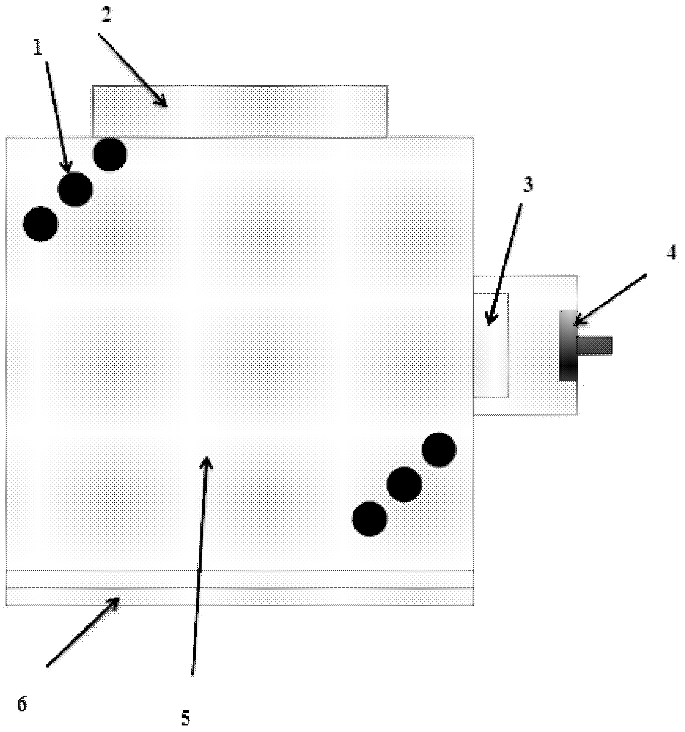
[0039] Acetylene gas is introduced into the coating chamber, and the high ionization rate of arc ion plating is used to evaporate Ti ions from the Ti target. At the same time, the strong plasma generated by arc discharge is used to ionize the acetylene passed into the vacuum chamber and dissociate the acetylene into C ions. And H ion. The C ions and Ti ions react on the surface of the Ti target to generate TiC; due to the strong affinity between Ti and C, finally the DLC phase will be formed between the TiC phases, thereby obtaining a titanium carbide-doped diamond-like film.

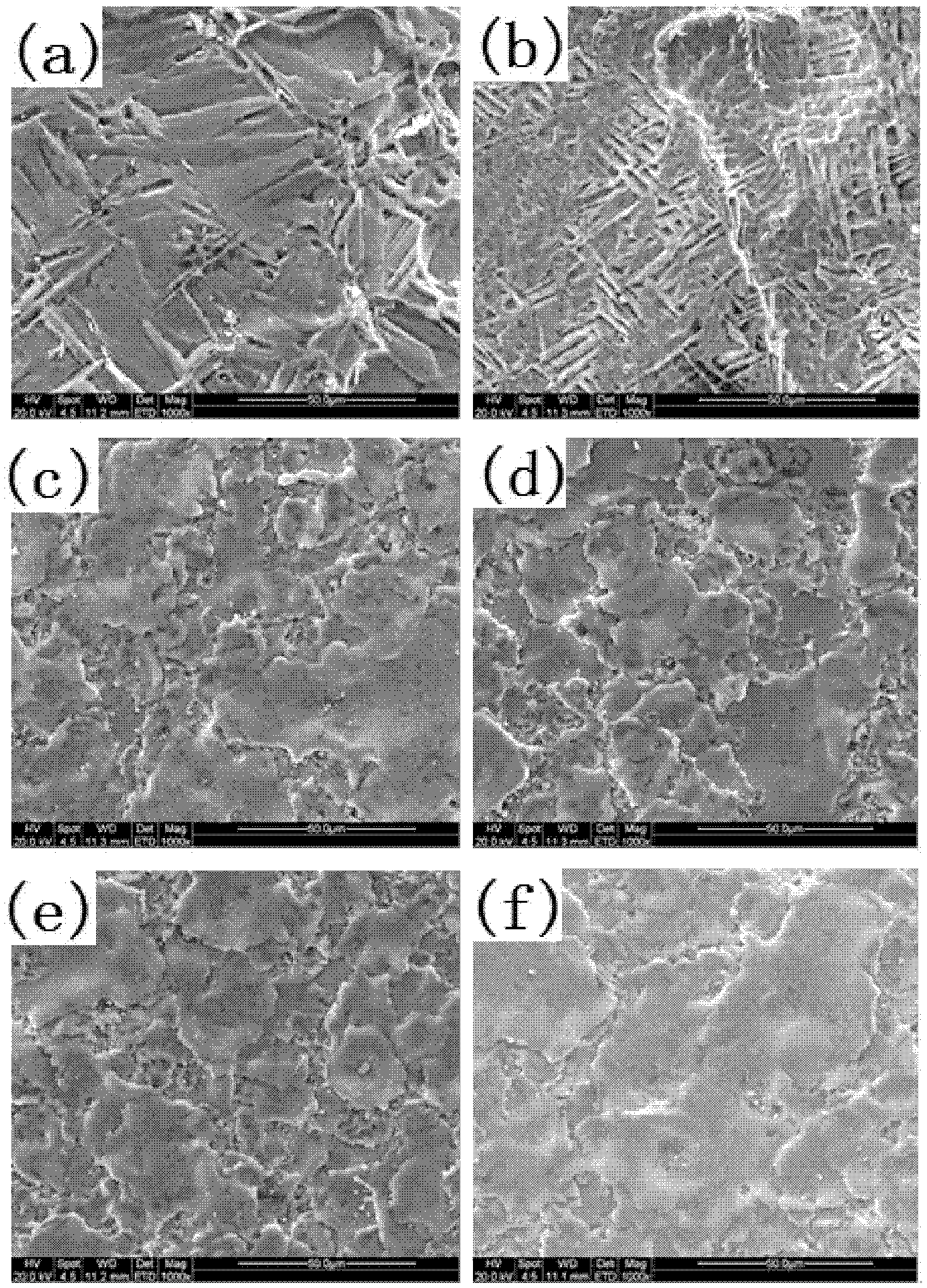
[0040] In this embodiment, the number of Ti target is one, it is disc-shaped, the bottom diameter is 100mm, and the thickness is 7.5mm; the flow rate of acetylene gas is 50sccm, 100sccm, 200sccm, 300sccm, 400sccm and 500sccm. The cathode discharge conditions of the Ti target are 1~3Pa, current is 50 amperes; synthesis time is 20 minutes, synthesis temperature is 150~300℃.

[0041] The surface SEM image and ...

Embodiment 2

[0048] Acetylene gas is introduced into the coating chamber, and the high ionization rate of arc ion plating is used to evaporate Ti ions from the Ti target. At the same time, the strong plasma generated by arc discharge is used to ionize the acetylene passed into the vacuum chamber and dissociate the acetylene into C ions. And H ion. The C ions and Ti ions react on the surface of the Ti target to generate TiC; due to the strong affinity between Ti and C, finally the DLC phase will be formed between the TiC phases, thereby obtaining a titanium carbide-doped diamond-like film.

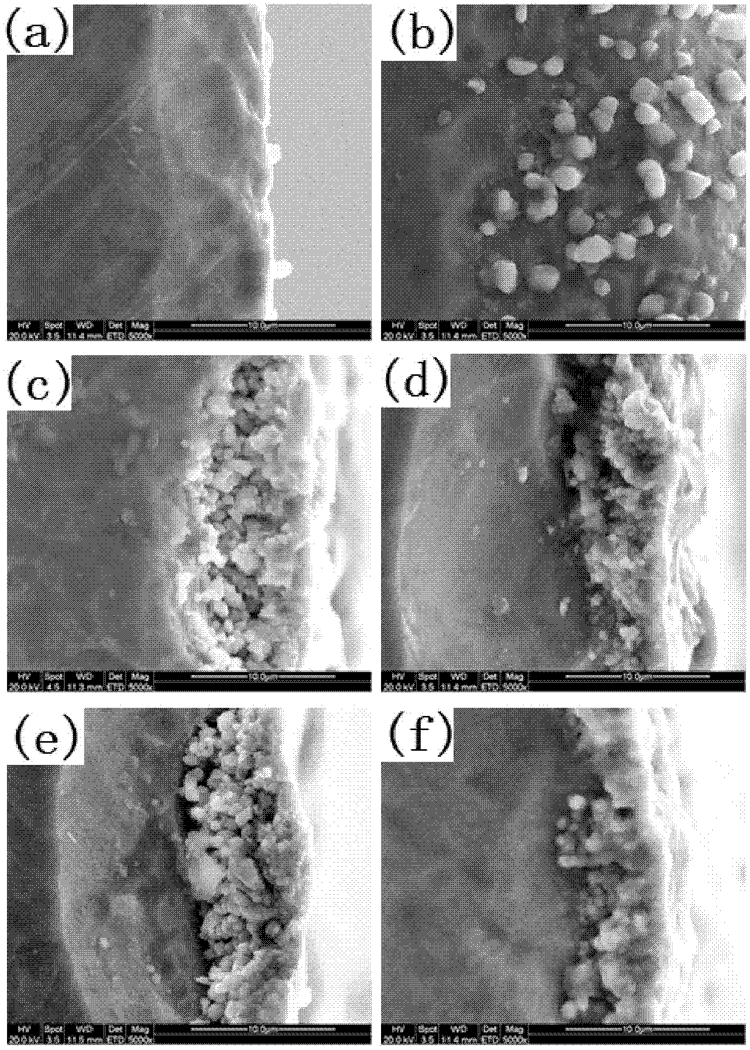
[0049] In this embodiment, the number of Ti target is one, it is disc-shaped, the bottom diameter is 100mm, the thickness is 7.5mm; the flow rate of acetylene gas is 400sccm; the cathode discharge condition of Ti target is 1~3Pa, the current is 50A; synthesis time Respectively 20, 30, 40, 50 and 60 minutes, the synthesis temperature is 150-300℃.

[0050] The surface SEM image of the TiC-DLC composite coatin...


PUM

PropertyMeasurementUnit
Thicknessaaaaaaaaaa
Grainaaaaaaaaaa

Abstract

The invention discloses a method for in-situ synthesis of a composite TiC-DLC coating on the surface of titanium. The method comprises the following steps of placing a Ti target in a coating chamber and introducing a hydrocarbon gas, vacuumizing the film plating chamber and maintaining the temperature of the coating chamber, evaporating Ti ions out from the Ti target by virtue of arc ion plating, and ionizing the hydrocarbon gas by virtue of arc discharge to form the composite TiC-doped DLC coating on the Ti target. According to the method, by adopting the in-situ synthesis technology, the composite coating is formed by direction chemical reaction on the surface of the Ti target material, the uniformity of the composition of the composite coating and the binding force of the coating can be significantly improved and the method has the advantages of simple preparation process, low cost and high efficiency and has good application prospects in the preparation of the DLC coating.

Description

Technical field [0001] The invention belongs to the technical field of thin film materials, and in particular relates to a method for in-situ synthesis of a TiC-DLC composite coating on the surface of titanium metal. Background technique [0002] Diamond-like carbon (DLC) film is a kind of sp 2 Key and sp 3 A mixed disordered metastable amorphous carbon film composed of bonds. In diamond, carbon atoms are 3 Bond, carbon atoms in graphite are sp 2 Bonding. Therefore, the structure and performance of the diamond-like film are between diamond and graphite, with high hardness, high elastic modulus, high wear resistance, low friction coefficient, and excellent corrosion resistance. Diamond-like carbon film is divided into hydrogen-containing amorphous carbon film (a-C:H) and hydrogen-free amorphous carbon film (a-C). Since DLC film was prepared by Aisenberg et al. using ion beam deposition in 1971, it has caused an upsurge in DLC film research around the world. At present, the prepa...

Claims


Application Information

Patent Timeline
IPC IPC(8): C23C14/32C23C14/06
Inventor 徐雅柔杨兵万强刘辉东罗畅陈燕鸣梅青松
Owner WUHAN UNIV
Why Eureka
Try Eureka