Multipoint-type catalytic biomass gasification machine

A biomass, multi-point technology, applied in the production of bulk chemicals, the manufacture of combustible gas, the petroleum industry, etc., can solve the problems of reducing the utilization rate of biomass raw materials, increasing the consumption of gas caused by cracking, and damage to gas utilization equipment, etc. The effect of reducing temperature, avoiding gas consumption, and leveling raw materials

Active Publication Date: 2014-11-19
甘肃华清新能源生物科技有限公司
View PDF5 Cites 2 Cited by
  • Summary
  • Abstract
  • Description
  • Claims
  • Application Information

AI Technical Summary

Problems solved by technology

However, the existing biomass gasifiers still have the following disadvantages: 1. The catalytic efficiency of the gasifier is low, and the gas production rate is slow, which increases the consumption of gas by cracking, which seriously restricts the development of large-scale biomass gasifiers ;2. The bulk density of raw materials in the fuel bunker is too low, resulting in uneven gas production and low gas production, which reduces the utilization rate of biomass raw materials; 3. The high tar content in the gasification process reduces the energy of combustible gas. After burning, it will produce harmful gas to the human body, which will seriously damage the gas utilization equipment and increase the maintenance cost of the equipment

Method used


Image

  • Multipoint-type catalytic biomass gasification machine
  • Multipoint-type catalytic biomass gasification machine
  • Multipoint-type catalytic biomass gasification machine

Examples


Embodiment 1

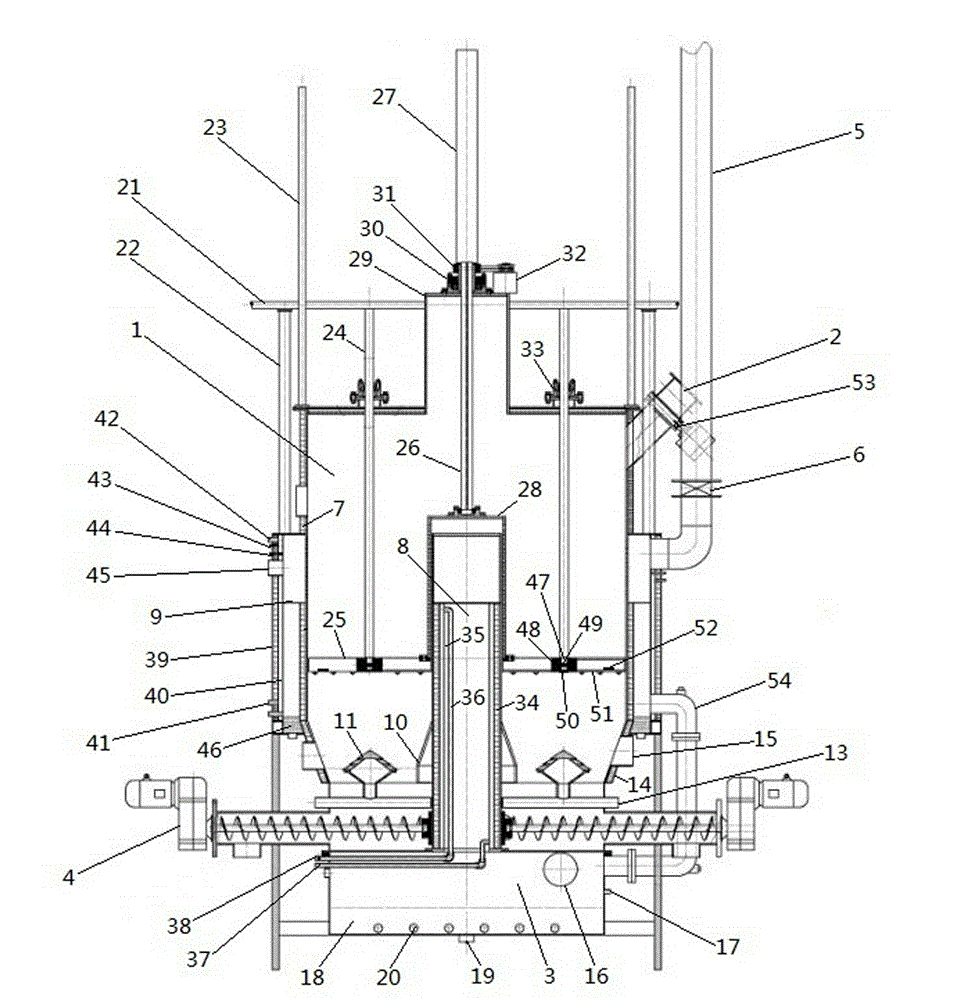
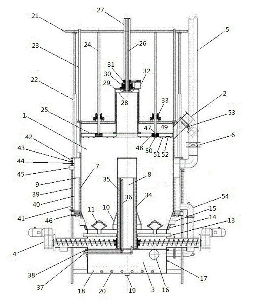
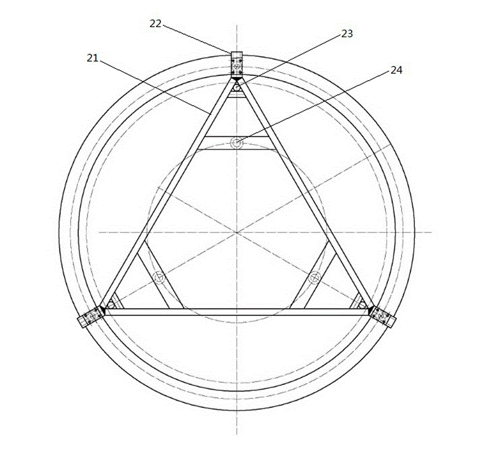
[0023] Example 1, such as figure 1 , figure 2 , image 3 , Figure 4As shown, a multi-point catalytic biomass gasifier includes a fuel bin 1, a feed port 2 arranged on the side of the fuel bin 1, a mixed gas bin 3 arranged at the lower part of the fuel bin 1, and a mixing chamber 3 arranged at the fuel bin 1 and The automatic slag discharge machine 4 between the gas bins 3, the top of the fuel bin 1 is equipped with a pressing system, the convection chimney 5 is installed under the feeding port 2, the vacuum butterfly valve 6 is installed on the convection chimney 5, and the inner wall of the fuel bin 1 is equipped with an internal insulation Layer 7, an inner cooling gas bin 8 is arranged in the middle of the fuel bin 1, an outer cooling gas bin 9 is arranged on both sides of the fuel bin 1, a trapezoidal combustion chamber 10 is arranged in the middle of the bottom of the fuel bin 1, and tower-type cooling chambers are arranged around the trapezoidal combustion chamber 10...


PUM


Abstract

The invention relates to a multipoint-type catalytic biomass gasification machine which includes a fuel bin, a material adding opening arranged on a side surface of the fuel bin, a mixed gas bin arranged under the fuel bin and an automatically residue-discharging machine arranged between the fuel bin and the mixed gas bin. The multipoint-type catalytic biomass gasification machine is characterized in that a material-pressing system is disposed on the top of the fuel bin. An internal temperature-decreasing gas bin is disposed in the middle of the fuel bin and two external temperature-decreasing gas bins are respectively arranged on the two sides of the fuel bin. A trapezoid combustion chamber is disposed on the middle of the bottom of the fuel bin. Eight column-type oxygen homogenizing and distributing disks are arranged around the combustion chamber. An ignition hole is disposed above a gas inlet pipe. A gas outlet is disposed on a side surface above the mixed gas bin. A pyroligneous acid discharging outlet is disposed under the gas outlet. A sewage discharging hole and a tar discharging hole are arranged on the top of the mixed gas bin. By means of the eight column-type oxygen homogenizing and distributing disks, oxygen is fed into the fuel bin uniformly. By means of multipoint-type catalysis, a gas output speed is increased and a gas production amount is increased so that a biomass fuel is saved. The invention can satisfy a production requirement of a large-scale gasification machine. By means of quick temperature decrease, sedimentation speed of tar and dust can be increased so that fuel gas is more pure.

Description

technical field [0001] The invention belongs to biomass gasification equipment, in particular to a multi-point catalytic biomass gasification machine with rapid gas production, large gas production capacity and fuel saving. Background technique [0002] At present, my country's energy consumption ranks first in the world, CO 2 Emissions are second only to the United States, and are expected to overtake the United States in 2015 to become the world's largest emitter. In addition, it is estimated that by 2020, my country's crude oil imports will reach 250 million tons, and natural gas will reach 150 billion cubic meters, surpassing my country's 50% of energy consumption, my country's excessive dependence on imported energy directly threatens my country's energy security. With the rapid growth of energy consumption, the extensive use of fossil fuels will bring serious environmental pollution and ecological damage, resulting in frequent occurrence of smog air and heavy metal pol...

Claims


Application Information

Patent Timeline
Patent Type & Authority Applications(China)
IPC IPC(8): C10J3/20C10J3/72C10J3/84
CPCY02P20/52
Inventor 陆福明
Owner 甘肃华清新能源生物科技有限公司
Why Eureka
Try Eureka