
Folding gate-controlled L-shaped channel tunneling transistor low in leakage current

A technology of tunneling transistors and low leakage, applied in thyristors, circuits, electrical components, etc., can solve the problems of large static power consumption, weakened gate electrode control ability, and cannot be reduced, achieve fast current rise rate, and overcome sub-threshold characteristics The effect of enhancing the control effect

Inactive Publication Date: 2015-01-14
SHENYANG POLYTECHNIC UNIV
View PDF4 Cites 0 Cited by
  • Summary
  • Abstract
  • Description
  • Claims
  • Application Information

AI Technical Summary

Problems solved by technology

The disadvantage of the current tunneling transistor manufactured according to the existing technology is that the gate electrode voltage can generate a considerable tunneling current when it is forward-biased and reverse-biased, which makes the static power consumption of the tunneling transistor larger. At the same time, Tunneling transistors manufactured by existing planar technology are similar to MOSFETs. When the channel length of the device is too short, the subthreshold characteristics decrease due to the weakening of the gate electrode control ability and the channel voltage caused by the drain voltage. Dow barrier lowering effect (DIBL) and other issues
[0003] Increasing the dielectric constant of the gate insulating layer can enhance the control ability of the gate electrode to short-channel TFETs devices, improve subthreshold characteristics and solve problems such as DIBL. The problem of generating a large tunneling current, so instead of reducing but increasing the static power consumption of the tunneling transistor

Method used


Image

  • Folding gate-controlled L-shaped channel tunneling transistor low in leakage current
  • Folding gate-controlled L-shaped channel tunneling transistor low in leakage current
  • Folding gate-controlled L-shaped channel tunneling transistor low in leakage current

Examples


Embodiment Construction

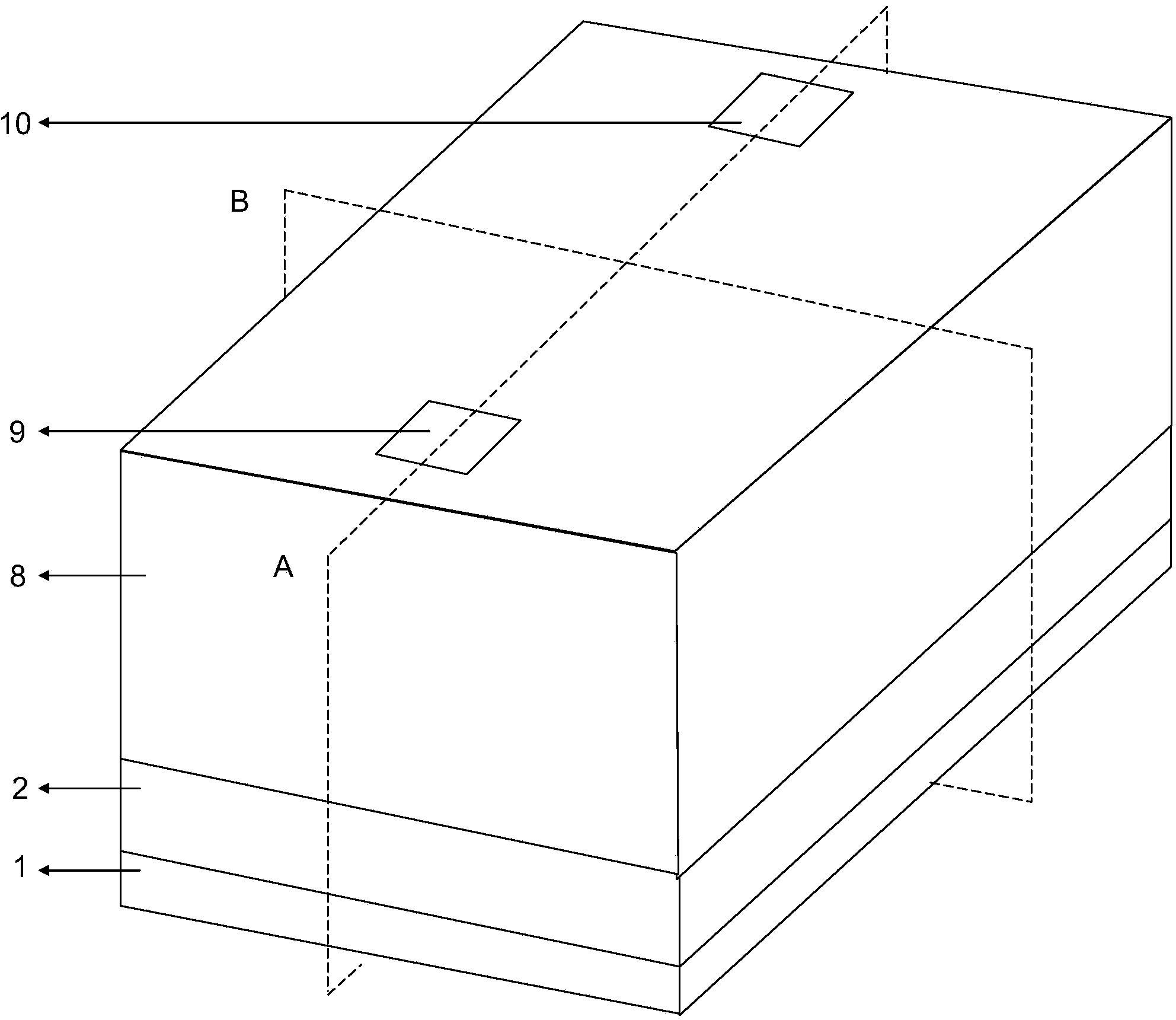
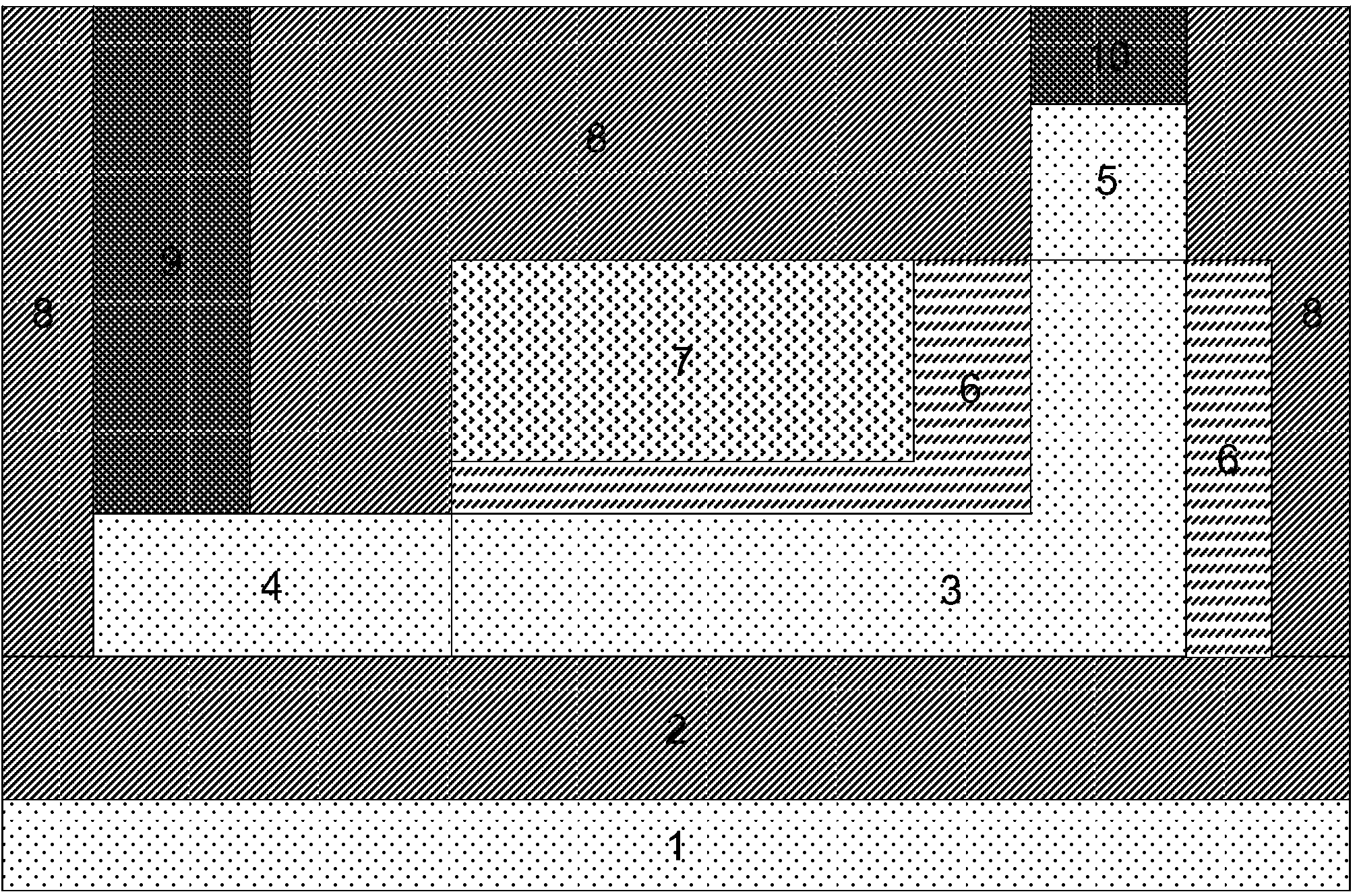
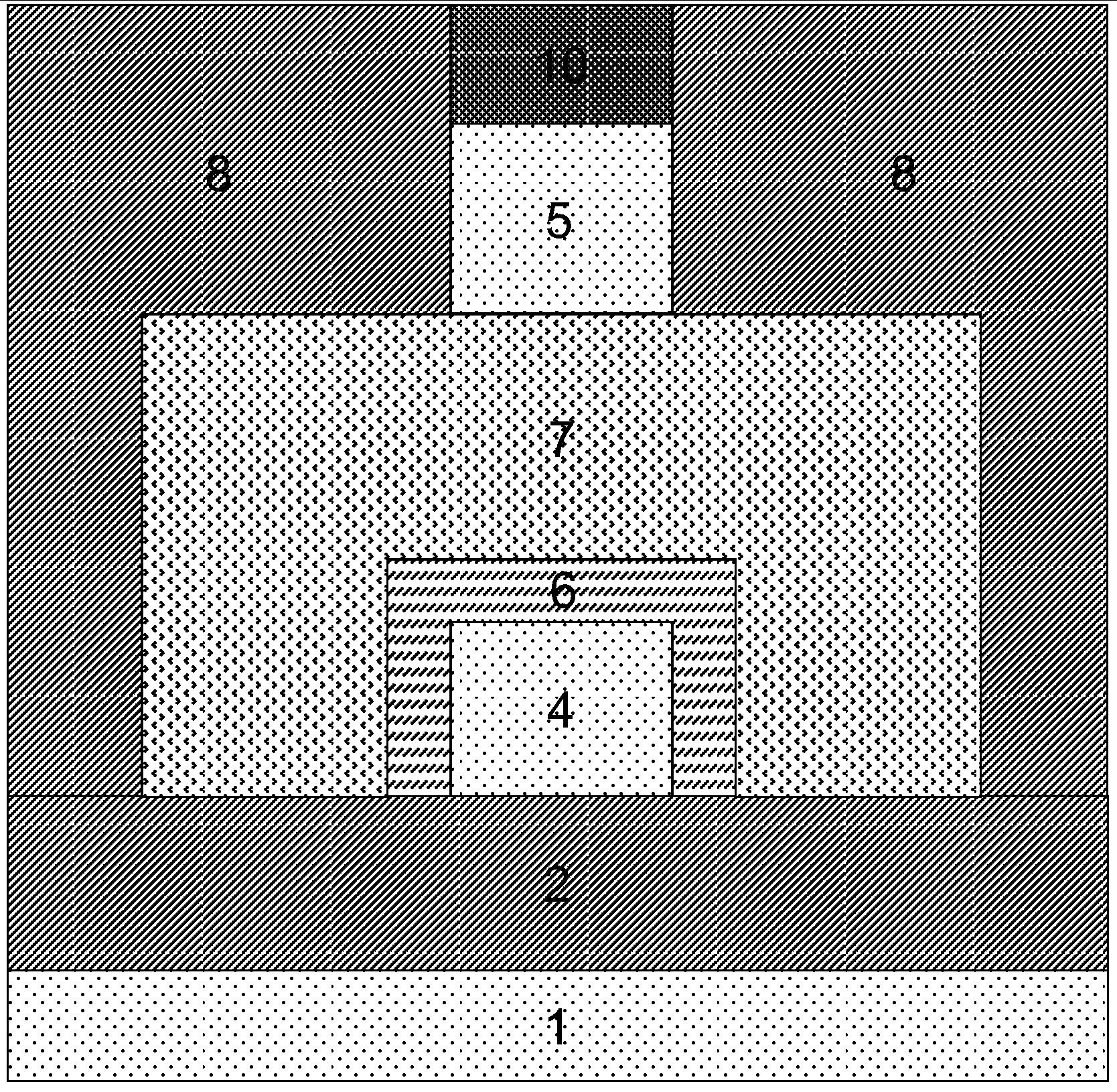
[0030] The folded gate electrode 7 is located above and on both sides of the horizontal part of the L-shaped intrinsic silicon 3, is isolated from the L-shaped intrinsic silicon 3 by the gate insulating layer 6, and has a control effect.

[0031] The thickness of the gate insulating layer 6 between the folded gate electrode 7 and the horizontal part of the L-shaped intrinsic silicon 3 is between 0.4 nanometers and 2 nanometers; between the folded gate electrode 7 and the vertical part of the L-shaped intrinsic silicon 3 The thickness of the intervening gate insulating layer 6 is between 2 nanometers and 4 nanometers.

[0032] The gate insulating layer 6 is an insulating medium with a high dielectric constant, and the insulating medium may be hafnium dioxide, silicon nitride, aluminum oxide and the like.

[0033] The dielectric constant of the insulating dielectric layer 8 is lower than that of the gate insulating layer 6 and may be silicon nitride, silicon dioxide or the like...


PUM


Abstract

The invention relates to a folding gate-controlled L-shaped channel tunneling transistor low in leakage current. By the adoption of the structural design of a folding gate electrode, the horizontal part and the vertical part of L-shaped intrinsic silicon can be controlled at the same time. By the adoption of the structural design of the L-shaped intrinsic silicon, a device has the higher current rise rate in a subthreshold region and the higher forward break-over capacity, and the band bending near a drain area generated when the device is in the reverse bias state is greatly retarded. Thus, compared with a common tunneling transistor, it is guaranteed that the device has better forward characteristics, lower reverse leakage current and lower static power consumption. The invention further relates to a specific manufacturing method of a device structure unit. The folding gate-controlled L-shaped channel tunneling transistor low in leakage current and the specific manufacturing method of the device structure unit are suitable for application and popularization.

Description

technical field [0001] The invention relates to the field of ultra-large-scale integrated circuit manufacturing, and relates to a specific structural unit and a manufacturing method of a folded gate-controlled L-shaped channel low-leakage current tunneling transistor suitable for ultra-high-integrated integrated circuit manufacturing. Background technique [0002] Currently, silicon-based PIN-type tunneling field-effect transistors (referred to as tunneling transistors) have the potential to achieve better switching characteristics and lower power consumption compared with traditional metal-oxide-semiconductor field-effect transistors (MOSFETs). , so it can replace MOSFETs and become one of the basic unit candidates of the new generation of integrated circuits. The disadvantage of the current tunneling transistor manufactured according to the existing technology is that the gate electrode voltage can generate a considerable tunneling current when it is forward-biased and re...

Claims


Application Information

Patent Timeline
Patent Type & Authority Applications(China)
IPC IPC(8): H01L29/739H01L29/423H01L29/10H01L29/08
CPCH01L29/083H01L29/1033H01L29/42356H01L29/7391
Inventor 靳晓诗吴美乐刘溪揣荣岩
Owner SHENYANG POLYTECHNIC UNIV
Learn More