MAG/MIG automatic welding device and method

An automatic welding and gas shielding technology, applied in welding equipment, welding connection methods, arc welding equipment, etc., can solve the problems of reducing welding residual stress and residual deformation, low welding productivity, and saving welding wire and electric energy. Reduced consumption of shielding gas, reduced welding production costs, and high mechanical properties of joints

Inactive Publication Date: 2015-01-21
武汉纳瑞格智能设备有限公司
View PDF7 Cites 16 Cited by
  • Summary
  • Abstract
  • Description
  • Claims
  • Application Information

AI Technical Summary

Problems solved by technology

Since the concept of "narrow gap welding" was proposed by American engineers in the early 1960s, after more than 50 years of development, it has become very mature and widely used. There are two main methods of narrow gap welding technology: narrow gap burying Arc welding and narrow gap argon arc welding, these two methods are arc welding, the former is slag wall transition, the latter is no droplet transition, the arc welding process is stable and reliable, and the welding productivity is improved compared with the traditional technology, However, the inherent limitations of their respective methods greatly restrict their wide application. For example, narrow gap submerged arc welding is basically used for flat welding, and it is difficult to be used for vertical welding, horizontal welding and other spatial positions; the reduction of the filling area of ​​welding groove is limited. , the saving of welding wire and electric energy is small; the welding heat input is large, and the mechanical properties of the welded joints are not ideal. Usually, the mechanical properties of the joints must be adjusted by post-weld heat treatment. This problem occurs when welding quenched and tempered high-strength steel and high-alloy steel. It is more prominent; due to the limited reduction of the filling area of ​​the welding groove, the reduction of welding residual stress and residual deformation is also very limited; and the wide application form of narrow gap argon arc welding is hot wire pulse argon arc welding, and its biggest limitation is welding productivity Too low, only equivalent to coated electrode arc welding, and has no competitiveness in the face of the huge welding engineering volume of large thick plate and ultra thick plate structure
It can not only effectively overcome the limitations of the above-mentioned narrow gap welding method, but also truly highlight the higher welding productivity of narrow gap welding technology. The history of research and development has been more than forty years, and a large number of research reports and patents have been produced, but so far it has not been applied in a real scale in the field of industrial production, let alone widely used. The reason is that the existing technology still exists. The stated limitations:
[0003] 1. The existing technology fails to solve the high stability of the arc work and the ultra-low welding spatter rate. The nozzle and the contact tip located in the narrow gap welding groove are very easy to destroy the protective gas flow state and stable wire feeding due to the accumulation of spatter. Cause interruption of welding process or unreliable protection of high temperature zone;
[0004] 2. The existing technology fails to solve the problem of high-reliability gas protection in the welding high-temperature zone in the narrow groove, resulting in a high defect rate of welding pores and a decrease in the metallurgical purity of the weld metal;
[0005] 3. Although the existing technology reproduces the research and development of the control technology for the adaptive tracking of the welding seam trajectory by the narrow gap welding torch under the narrow groove, it has not yet seen a narrow gap welding torch that fully adapts to the narrow gap groove and has high anti-interference ability and tracking accuracy. Adaptive tracking technology for gap MAG / MIG welding, which is the most important reason restricting the wide application of this technology;
[0006] 4. The prior art welding torch design optimization and manufacturing technology have not been matched with the high reliability requirements of narrow gap MAG / MIG welding;
[0007] 5. The perfect ultra-narrow gap MAG / MIG welding technology should be a systematic project, which must ensure that the five technical systems of power supply technology, gas shielding technology, welding seam track tracking technology, welding torch design and manufacturing technology, and welding process technology are coordinated and consistent. The development of welding technology under narrow gap MAG / MIG welding conditions is seriously lagging behind. For example, there is no single-sided welding and double-sided forming technology other than forced forming in the root bead, and there is no wave welding wire and swing arc in the uniform fusion control of the side wall. More reliable technology, etc., which is one of the reasons restricting the wide application of this technology

Method used


Image

  • MAG/MIG automatic welding device and method
  • MAG/MIG automatic welding device and method
  • MAG/MIG automatic welding device and method

Examples


Embodiment 1

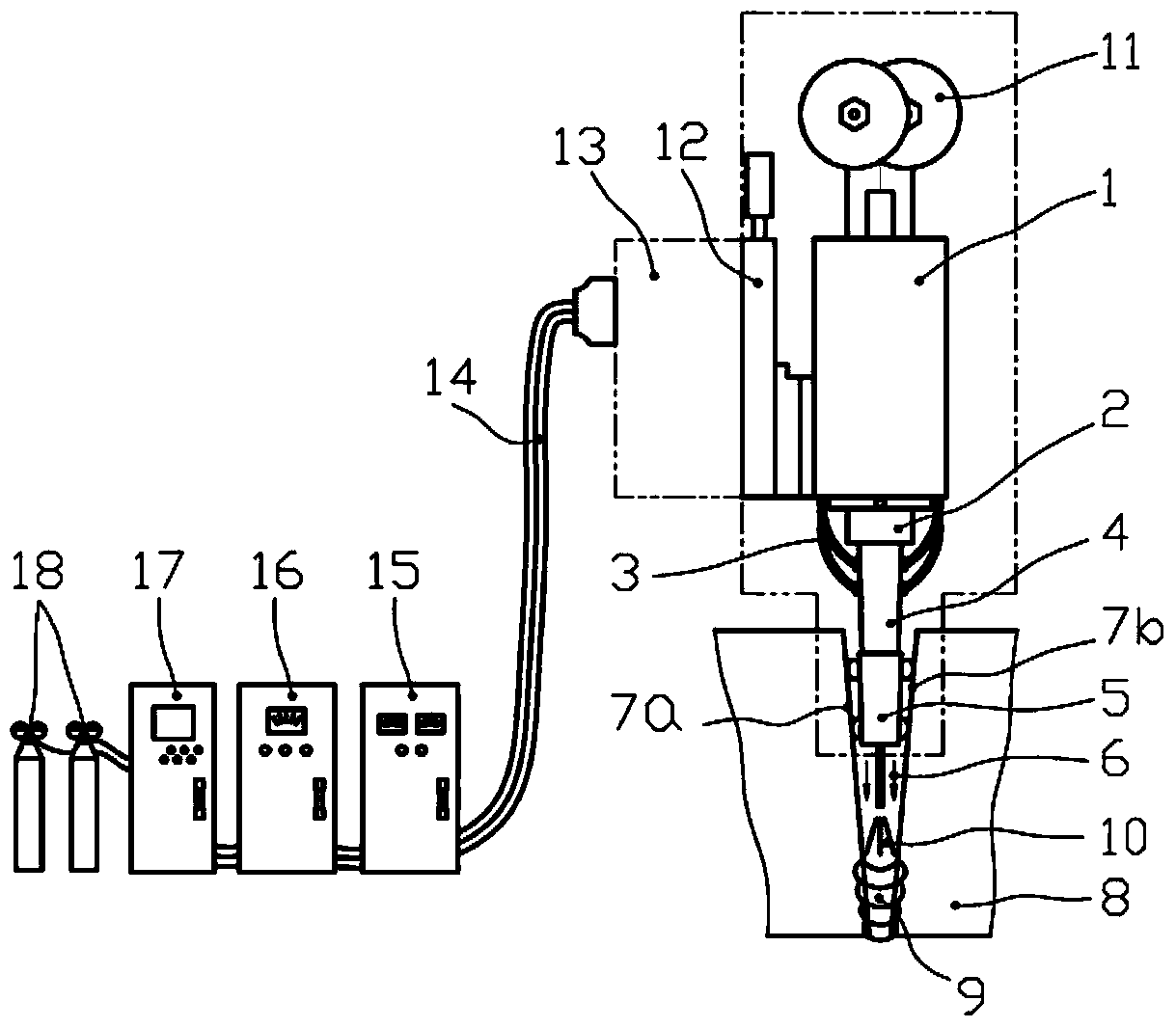
[0052] Example 1: is a basic embodiment of the present invention. Such as figure 1 , 4 , shown in 5, a kind of narrow gap / ultra-narrow gap gas-shielded automatic welding equipment includes a wire feeding mechanism 1, a wire reel 11 is installed on its top, and a three-dimensional self-adaptive centering device 2 is installed on the bottom; the three-dimensional self-adaptive centering The lower part of the device 2 is insulated and fixed an integral plate welding torch 4 whose outer layer has an insulating layer and the center line of the wire feeding channel coincides with the axis of the welding wire 6; There is a gas distribution device 20; the lower part of the gas distribution device 20 is connected to the protective nozzle 21; there are also water / gas pipelines 3, welding torch height adjustment mechanism 12, automatic welding operation mechanism 13, arc welding power supply 15 and cooling cabinet 16, and control Cabinet 17, control cables / welding cables 14 and shiel...

Embodiment 2

[0054] Example 2: is a further example. Such as figure 1 As shown, the narrow-gap / ultra-narrow-gap gas shielded automatic welding equipment has a welding torch height adjustment mechanism 12 connected to the wire feeding mechanism 1 for adjusting the wire feeding mechanism 1, the plate welding torch 4, and the three-dimensional self-adaptive centering device 2 and the exact height of the wire reel 11 along the thickness direction of the weldment 8; the ball screw can be driven by an AC servo motor, and the plate gun 4 is fixed on the screw nut; any other mechanism that can realize the above-mentioned transmission function can also be used; The height adjustment stroke of the plate welding torch 4 matches the maximum weldable plate thickness of the equipment model, and the stroke should generally be about 50mm greater than the maximum weldable piece 8 plate thickness.

[0055] Such as figure 1 As shown, the automatic welding manipulator 13 can be of different structural typ...

Embodiment 3

[0061] Example 3 : be the basic embodiment of the welding method with the narrow gap / ultra-narrow gap gas shielded automatic welding equipment of the present invention, comprising the following steps:

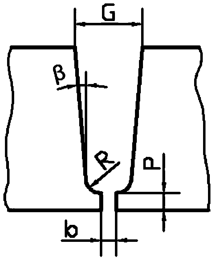
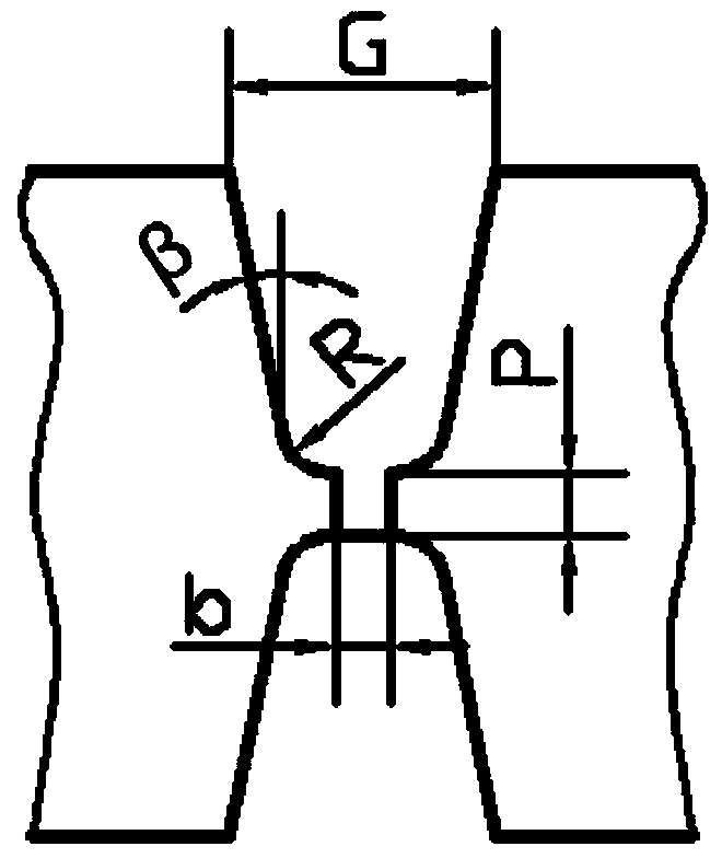
[0062] A. Determine the type and size of the welding groove;

[0063] B. Determine the side slip angle of the welding wire;

[0064] C. Determine the deposition method;

[0065] D. Determine the root assembly gap;

[0066] E. Determine the welding heat input and welding parameters of each layer.


PUM

PropertyMeasurementUnit
thicknessaaaaaaaaaa

Abstract

The invention relates to an MAG/MIG automatic welding device and method. The device comprises a wire feeding mechanism, a wire plate is installed at the upper portion of the wire feeding mechanism, and a three-dimensional self-adaptation centering device is installed at the lower portion of the wire feeding mechanism. A plate type welding gun is fixed to the lower portion of the centering device, and a self-adaptation centering sensor is installed at the lower portion of the plate type welding gun. A gas splitting device is arranged in the middle of the lower portion of the welding gun, and the lower portion of the splitting device is connected with a protection nozzle. A welding gun height adjusting mechanism is further included. The welding method includes the steps that welding groove types and sizes, welding wire slip angles and deposition manners are determined, and root gaps, the input power of all welding layers and welding parameters are determined. The MAG/MIG automatic welding device and method have the advantages that self-adaptation intelligent tracking of welding seam tracks under various MAG/MIG welding groove conditions can be achieved, the ultra low welding spattering rate is achieved, welding high-temperature areas under various welding technology conditions can be effectively and reliably protected, the device is durable, high in welding quality, stable, reliable and high in working efficiency, and the welding production cost is greatly lowered.

Description

technical field [0001] The invention relates to a narrow gap / ultra-narrow gap gas-shielded automatic welding equipment and welding method, which is narrow gap / ultra-narrow gap mixed gas shielded welding and inert gas shielded welding (NG / UNG-MAG / MIG), also known as narrow Gap / ultra-narrow gap (MAG / MIG) welding belongs to the field of welding technology. Background technique [0002] With the rapid development of science and technology and increasingly fierce market competition, modern industry has increasingly urgent requirements for higher production efficiency and lower production costs, which will lead to more and more modern industrial equipment such as chemical equipment, energy equipment, transportation equipment, and national defense equipment. The biggest problem of high-parameterization and large-scale equipment manufacturing is the huge amount of welding engineering, and the contradiction between welding efficiency and manufacturing cycle is becoming increasingly a...

Claims


Application Information

Patent Timeline
Patent Type & Authority Applications(China)
IPC IPC(8): B23K9/16B23K9/28B23K9/32B23K9/095
CPCB23K9/16B23K9/0213B23K9/12B23K9/133B23K9/323
Inventor 张富巨张瑞王宇飞何浩李志勇
Owner 武汉纳瑞格智能设备有限公司
Why Eureka
Try Eureka