Optical fiber preform manufacturing method

An optical fiber preform and a manufacturing method technology, which are applied to manufacturing tools, glass manufacturing equipment, glass deposition furnaces, etc., can solve the problem that the shape of the end face of the powder preform has a large deviation from the set shape and is not suitable for the control parameters of the outer diameter of the powder preform. , reduce the control accuracy and other problems, to achieve the effect of high precision and anti-interference ability, reduce the mutual interference of flames, and improve the control effect

Inactive Publication Date: 2015-02-18
TONGDING INTERCONNECTION INFORMATION CO LTD
View PDF6 Cites 21 Cited by
  • Summary
  • Abstract
  • Description
  • Claims
  • Application Information

AI Technical Summary

Problems solved by technology

[0011] 1. During the deposition process, the deposition chamber is filled with suspended solid particles, which will cause large background noise in the image acquisition process of the CCD imager, affect the quality of the acquired image, and then reduce the control accuracy;
[0012] 2. There will be a tailing effect during the blowtorch deposition process, that is, a large amount of fluffy loose body will be deposited at the far end of the deposition surface, and the second blowtorch will deposit the cladding layer at the outer end of the deposited core l

Method used


Image

  • Optical fiber preform manufacturing method
  • Optical fiber preform manufacturing method
  • Optical fiber preform manufacturing method

Examples


Embodiment 1

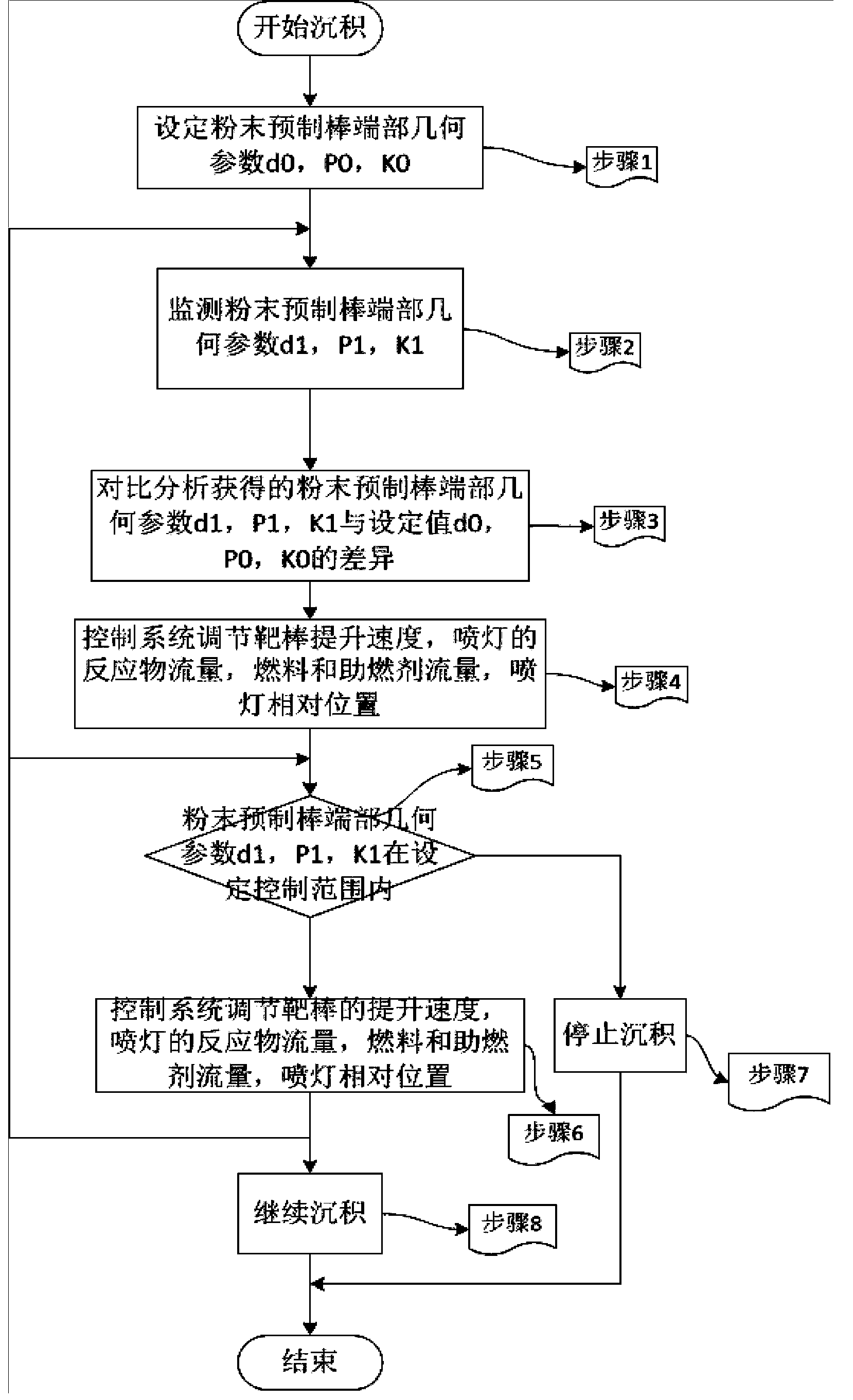
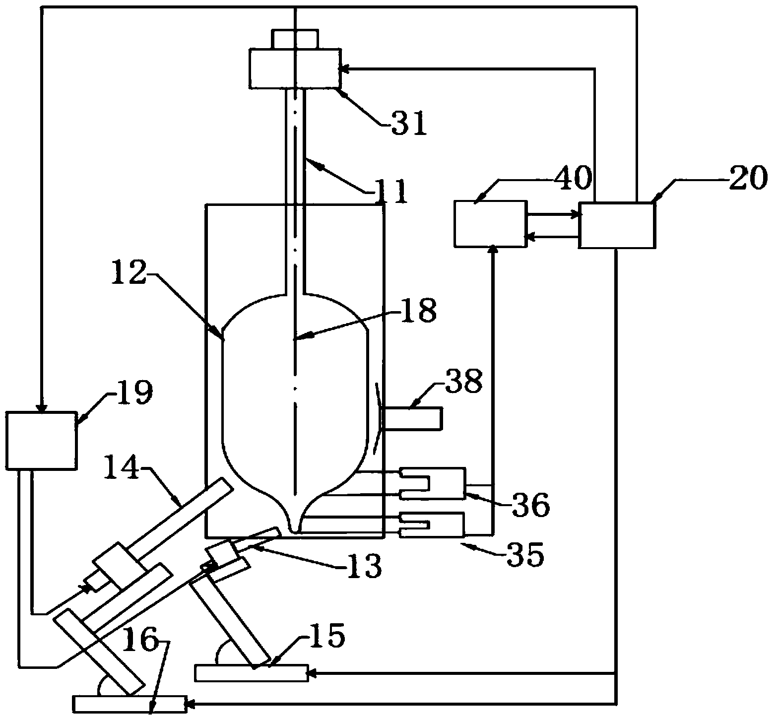
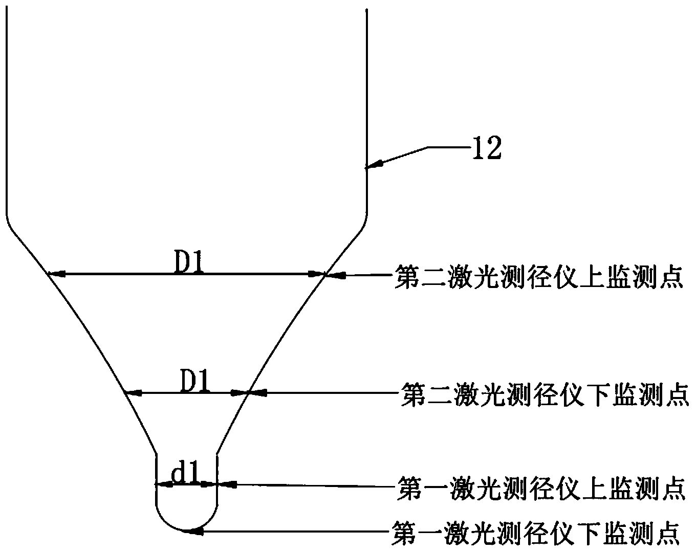
[0065] a. Example 1: Traditional method: In the VAD method, a high-purity quartz target rod with a diameter of 35mm is used, and two torches are used to deposit the core layer and the cladding powder layer respectively, where the core layer is SiO 2 With Geo 2 Mixture, cladding is SiO 2 Powder, the average density of powder preform is 0.28gram / cm 3 , The length of the uniform part of the outer diameter of the powder body is 1000mm; the median value P0 of the geometric parameter setting value of the top of the powder preform is 2.5, and the control range of P0 is 2-3; the geometric parameters of the top of the powder preform are measured in real time by the measurement system, and the measurement result is analyzed by the analysis system Perform analysis and calculation, where the measurement system is composed of a first laser diameter gauge and a second laser diameter gauge;

[0066] After the deposition, the powder preform is transferred to the conveying platform of the dehydrati...

Embodiment 2

[0069] c. Example 2: Traditional method: In the VAD method, a high-purity quartz target rod with a diameter of 30mm is used, and two torches are used to separately deposit the core layer and the cladding powder layer, where the core layer is SiO 2 With Geo 2 Mixture, cladding is SiO 2 Mixture with F, the average density of powder preform is 0.25gram / cm 3 , The length of the powder body is 1000mm; the d0 of the geometric parameter setting value of the top of the powder preform is 30mm, and the control range of d10 is 28mm-32mm; the geometric parameters of the top of the powder preform are measured in real time by the measurement system, and the analysis system analyzes the measurement results Calculation, where the measurement system consists of the first laser diameter gauge and the second laser diameter gauge;

[0070] After the deposition is completed, the powder preform is transferred to the conveying platform of the dehydration sintering furnace, the preform is extended into th...


PUM


Abstract

The invention discloses an optical fiber preform manufacturing method which comprises the following steps: an upper laser of a first laser instrument measures the diameter d of a sandwich layer, a lower laser measures the top end shape P of a powder preform, and a system determines the withdrawal rate of the powder preform according to the top end shape P; an upper laser and a lower laser of a second laser instrument measure diameters of an upper point and a lower point of a coating layer respectively to further calculate the slope K of the deposition coating layer. An analytical system compares the differences between the actual parameters d1, P1 and K1 and the set parameters d0, P0 and K0 of the deposition powder preform. During the deposition process of the powder preform, a measuring system (a laser diameter measuring instrument), a control system and the analytical system are in closed cycle, the system is in real-time measurement, analysis and adjustment processes, and the deposition process can be controlled through the K value at the initial period when the top end shape of the coating layer deviates from the control mid-value so as to obtain the coating layer with uniform external diameter and improve the quality of the powder preform.

Description

Technical field [0001] The invention relates to a method for preparing a large-size ultra-low water peak optical fiber preform by a gas phase axial method, in particular to a method for manufacturing an optical fiber preform; Background technique [0002] Optical fiber is the basis of modern communication, and optical fiber preform is the main raw material for drawing optical fiber. At present, the preparation method of commercial preform generally adopts a "two-step" manufacturing process, that is, the first step is the preparation of the core rod; the second step, The mandrel is covered with a cladding and formed into a rod; among them, typical mandrel manufacturing processes include: PCVD (plasma chemical vapor deposition) plasma excited chemical vapor deposition, MCVD (modified chemical vapor deposition) improved chemical vapor deposition, OVD ( outside vapor deposition method and VAD (vapor axial deposition) vapor axial deposition method; among them, PCVD and MCVD are collec...

Claims


Application Information

Patent Timeline
IPC IPC(8): C03B37/018
CPCC03B37/018C03B37/01853C03B2201/12C03B2201/31C03B2207/12C03B2207/36
Inventor 沈小平王强强吴仪温范修远张亮李震宇蒋小强
Owner TONGDING INTERCONNECTION INFORMATION CO LTD
Why Eureka
Try Eureka