
Method for remediating pond water in situ

A technology for in-situ remediation and water body application in chemical instruments and methods, biological water/sewage treatment, water/sludge/sewage treatment, etc. A large workload and other problems, to achieve the effect of stable repair effect, no secondary pollution, and reduce follow-up investment

Inactive Publication Date: 2015-03-04
GUANGXI UNIV
View PDF2 Cites 9 Cited by
  • Summary
  • Abstract
  • Description
  • Claims
  • Application Information

AI Technical Summary

Problems solved by technology

Its disadvantages are: slow diffusion of microbial concentration, poor impact resistance, and serious loss of bacteria
The disadvantage is that the workload of screening, separating and purifying suitable microbial strains is large, and the production cost of immobilized carriers is relatively high

Method used


Image

  • Method for remediating pond water in situ

Examples


Embodiment 1

[0019] Embodiment 1: Carry out the simulated restoration experiment of eutrophic lake pond water body with the inventive method

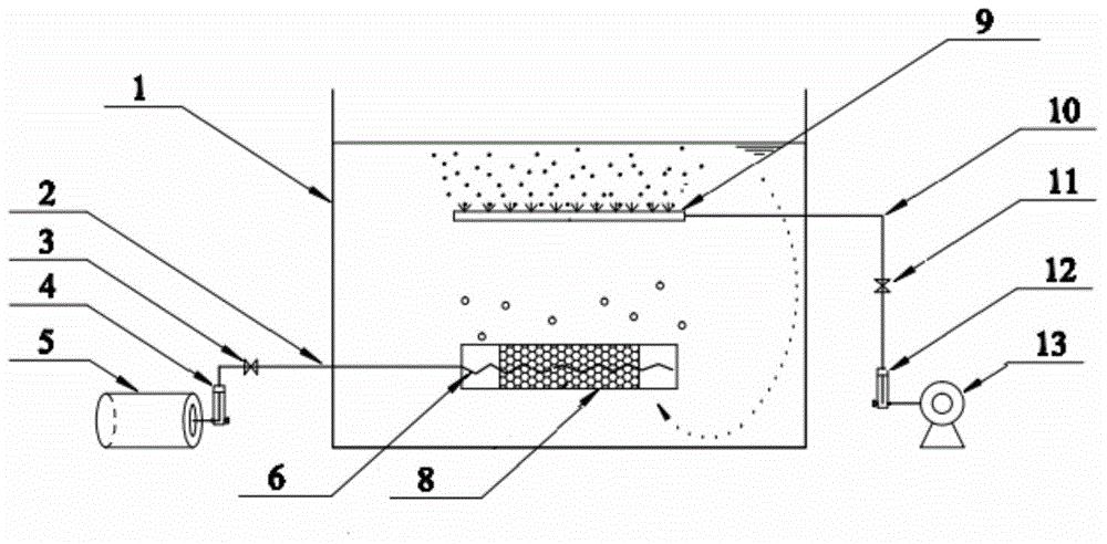
[0020] figure 1 It is a graphic representation of the simulated restoration experiment of the eutrophic lake and pond water body carried out by the method of the present invention. The biochemical reaction tank 1 is a PVC barrel with a height of 800mm, a bottom of Φ400mm, and an upper opening of Φ600mm. 150L of natural lake water to be repaired is added to the barrel at one time, and the water quality is COD: 35mg / L, NH 4 -N: 15mg / L, pH: 7.5, DO: 1.2mg / L. The barrel is arranged in a suspended manner, from top to bottom, there are microporous aeration head 9 and BC biological reaction system. The microporous aeration head 9 adopts a corundum-type straight-discharge aeration head with a pore diameter of 180 μm, and its upper edge is located 200 mm below the water surface, and is connected to an air compressor 13 through an air supply pipe 10, which ...

Embodiment 2

[0024] Lakes and ponds to be repaired, with an average water depth of 1.0m and a water area of ​​about 200m 2 , where the COD concentration is 40mg / L, the ammonia nitrogen concentration is 9.4mg / L, and the total phosphorus concentration is 0.6mg / L. The main source of water in the pond is the surrounding surface precipitation runoff, which is a typical closed landscape water body. The source of pollution is the release of sediment, rainwater entrainment, aquatic organisms, and plant residues at the waterside. The method of the present invention is used for in-situ restoration of lake and pond water bodies. The microporous aeration head 9 adopts a corundum disc aeration head with a pore diameter of 180 μm. The power of the air compressor 13 is 180W, and the displacement is 220L / min. All the other are with embodiment 1. And set up three monitoring points at the main water inlets and overflow weirs in lakes and ponds.

[0025] Through 30 consecutive days of lake and pond water ...


PUM

PropertyMeasurementUnit
diameteraaaaaaaaaa
lengthaaaaaaaaaa

Abstract

The invention discloses a method for remediating pond water in situ. The method comprises the following steps: suspending a surface aeration system and a BC biological reaction system in water from top to bottom in sequence, wherein the surface aeration system is used for rising and diffusing water, and the BC biological reaction system is used for immobilizing microorganisms; performing rising movement on the water from the lower part of the water under the action of rising force provided by the surface aeration system; passing the water through the BC biological reaction system, and activating immobilized microorganisms in the BC biological reaction system by nutrient substances in water to breed; pushing out the rising water body by the surface aeration system, and circulating the water to the bottom of the pond under the action of water flow density difference. The method for in-situ remediating pond water disclosed by the invention has the advantages that the starting is quick, the needed remediating time is short, the concentration of the microorganisms is high, the bottom sludge is synchronously degraded, the process operation is simple, the energy consumption is low, the secondary pollution is avoided and the remediating effects are stable.

Description

technical field [0001] The invention belongs to the field of in-situ restoration and purification of lake and pond water bodies, and in particular relates to a method for in-situ restoration of lake and pond water bodies. technical background [0002] Among the existing in-situ restoration technologies for lakes and ponds, there are physical restoration, such as sediment dredging, water diversion dilution, etc.; chemical restoration, such as flocculation, sedimentation, complexation, etc.; biological restoration, such as phytoremediation and microbial restoration. Among them, microbial remediation technology has been widely used in recent years, which can be divided into suspension type, attachment type and fixed type according to the existence form of microorganisms. [0003] The suspension type usually uses liquid or powder microbial preparations or microbial accelerators directly injected into the water body. After the former enters the water body environment, the microor...

Claims


Application Information

Patent Timeline
Patent Type & Authority Applications(China)
IPC IPC(8): C02F3/32C02F3/30
Inventor 冼萍刘熹黄世钊赵黔
Owner GUANGXI UNIV
Learn More