

Method for accurately calibrating optical constant of visible light waveband of optical thin film
A technology of optical constants and optical thin films, which is applied in the field of accurate calibration of optical constants in the visible light band of optical thin films
- Summary
- Abstract
- Description
- Claims
- Application Information
AI Technical Summary
Problems solved by technology
Method used
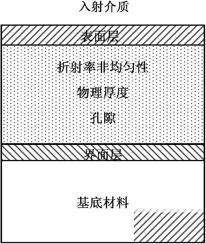
Image

Examples
Embodiment 1
[0050] Accurate calibration of optical constants of silicon dioxide thin films prepared by electron beam:
[0051] 1) Si substrate with ultra-smooth surface, surface roughness ~ 0.3nm, size Φ40×0.30mm, SiO prepared by electron beam evaporation 2 film;
[0052] 2) Electron beam evaporation of SiO 2 The material of the film is high-purity ultraviolet fused silica, the purity is ≥99.995%, and the vacuum degree of the back and bottom is better than 1.0×10 -3 Pa, the substrate temperature is 200°C, the deposition rate is 0.3nm / s, the film thickness is monitored by IC5 crystal vibration, and the physical thickness is 1500nm;
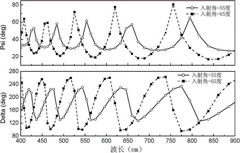
[0053] 3) Use an ellipsometer to measure the reflection ellipsometric parameters Ψ(λ) and Δ(λ) of the silica film, set the measurement wavelength range to 400nm-800nm, the measurement step size to 5nm, and the incident angles to be 55° and 65° . The ellipsometer uses the VASE type variable incidence angle ellipsometer of J.A.Woollam Company of the United S...
Embodiment 2
[0059] Precise Calibration of Optical Constants of SiO2 Thin Films Prepared by Ion Beam Sputtering:
[0060] 1) Si substrate with ultra-smooth surface, surface roughness ~ 0.3nm, size Φ40×0.30mm, prepared SiO by ion beam sputtering deposition method 2 film;
[0061] 2) SiO deposited by ion beam sputtering 2 The film adopts high-purity ultraviolet fused silica target material, the purity is ≥99.995%, and the vacuum degree of the back and the bottom is better than 1.0×10 -3 P, the ion beam voltage is 1250V, the ion beam current is 600mA, the oxygen flow rate is 25sccm, and the deposition time is 1h;
[0062] 3) Use an ellipsometer to measure the reflection ellipsometric parameters Ψ(λ) and Δ(λ) of the silica film, set the measurement wavelength range to 400nm-800nm, the measurement step size to 5nm, and the incident angles to be 55° and 65° . The ellipsometer uses the VASE type variable incidence angle ellipsometer of J.A.Woollam Company of the United States. attached Fig...
PUM
| Property | Measurement | Unit |
|---|---|---|
| Roughness | aaaaa | aaaaa |
Abstract
Description
Claims
Application Information