Biological enhanced nitrogen removal treatment method of degradation-resistant high-concentration organic industrial wastewater

A technology for industrial wastewater and biological enhancement, applied in natural water treatment, water treatment parameter control, chemical instruments and methods, etc., can solve the problems of secondary pollution, high operating costs, and difficulty in control.

Active Publication Date: 2015-05-20
EAST CHINA UNIV OF SCI & TECH
View PDF3 Cites 2 Cited by
  • Summary
  • Abstract
  • Description
  • Claims
  • Application Information

AI Technical Summary

Problems solved by technology

At present, the commonly used sludge source reduction method is to decompose the excess sludge by adding decoupling agent or ozone oxidation, ultrasonic method, etc. in the system, and then return it to the aeration tank to

Method used


Image

  • Biological enhanced nitrogen removal treatment method of degradation-resistant high-concentration organic industrial wastewater
  • Biological enhanced nitrogen removal treatment method of degradation-resistant high-concentration organic industrial wastewater
  • Biological enhanced nitrogen removal treatment method of degradation-resistant high-concentration organic industrial wastewater

Examples


Example Embodiment

[0028] Example 1

[0029] In this embodiment, the sewage is first homogenized (to make the waste water evenly mixed), and then subjected to secondary precipitation after passing through the secondary anoxic-aerobic + biofilm component reactor.

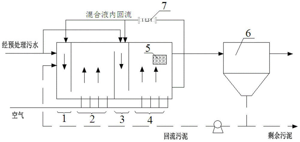
[0030] The processing system used in this embodiment is such as figure 1 As shown, the first-level anoxic tank 1, the first-level aerobic tank 2, the second-level anoxic tank 3, and the second-level aerobic tank 4 are connected in sequence, 0.3 meters below the liquid surface of the second-level aerobic tank 4 A biomembrane module 5 with a thickness of 0.5m is added at the place, covering an area of ​​1 / 3 of the total length of the tank and 9 / 10 of the total width, located at the end of the tank, and the distance between the upper surface of the module and the sewage surface is 0.3 meters. The outlet water of the second-stage aerobic tank 4 is connected to the second settling tank section 6. The effluent of the second-stage aerobic tank 4 ...

Example Embodiment

[0037] Example 2

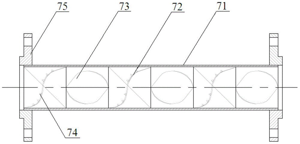
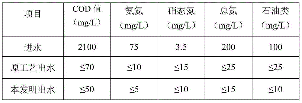
[0038] The total nitrogen and COD of a coal-to-gas wastewater of a coal chemical plant cannot meet the standards stably using the original treatment technology. After adopting this technical transformation, the main process route is as follows: First, the sewage passes through the anaerobic digestion section to remove a large amount of organic pollutants, so that the influent COD is maintained at about 500mg / L, and then enters the first level at a ratio of 7:3. , The secondary anoxic tank, and then the mud-water mixture in the same proportion passes through the tubular sludge crusher and then enters the anoxic tanks at all levels. The sludge is sheared and broken by strong turbulence, and the surface of the flocs is destroyed, releasing organic matter such as polysaccharides and proteins. , To supplement the organic carbon source required for denitrification in anoxic tanks to strengthen denitrification, degradation of refractory organic matter and reduction of...

Example Embodiment

[0047] Example 3

[0048] A treatment method for bio-enhanced denitrification of refractory high-concentration organic industrial wastewater. The treatment system used is such as figure 1 As shown, the first-level anoxic tank 1, the first-level aerobic tank 2, the second-level anoxic tank 3, and the second-level aerobic tank 4 are connected in sequence, 0.3 meters below the liquid surface of the second-level aerobic tank 4 A biomembrane module 5 with a thickness of 0.5m is added at the place, covering an area of ​​1 / 3 of the total length of the tank and 9 / 10 of the total width, located at the end of the tank, and the distance between the upper surface of the module and the sewage surface is 0.3 meters. The outlet water of the second-stage aerobic tank 4 is connected to the second settling tank section 6. The effluent of the second-stage aerobic tank 4 is respectively returned to the first-stage anoxic tank 1 and the second-stage anoxic tank 3 through the return pipeline. A tubula...


PUM

PropertyMeasurementUnit
Particle sizeaaaaaaaaaa

Abstract

The invention relates to a biological enhanced nitrogen removal treatment method of degradation-resistant high-concentration organic industrial wastewater. The method comprises the following steps that biological enhanced nitrogen removal on sewage is carried out by using a device in which anoxic tanks and aerobiotic tanks are alternately distributed, continuously arrayed and are communicated with one another to ensure that raw water of the sewage separately flows into the anoxic tanks and effluent water from a tail-ended aerobiotic tank flows back to the anoxic tanks respectively through a backflow pipeline; a pipe type sludge crushing device is arranged on the backflow pipeline to ensure that organic matters contained in the sludge floc are exposed and released, and organic carbon sources of the anoxic tanks are supplemented along with backflow liquid, so that the denitrification efficiency is improved. Compared with the prior art, the biological enhanced nitrogen removal treatment method has the advantages that the pipe type sludge crushing device is additionally arranged, so that the decrement of the sludge sources is completed, the degradation capability of degradation-resistant organic matters by the sludge floc is also enhanced. By optimizing raw-water and water-inlet rate of a secondary anaerobic-aerobic technical process and equinoctial backflow rate, a biological membrane assembly is additionally arranged at the tail end of a secondary aerobiotic tank, so that the nitration efficiency of an aerobiotic work section is effectively improved, and the COD value, the ammonia nitrogen content and the total nitrogen level are relatively low.

Description

Technical field [0001] The invention relates to a method for biological denitrification of sewage, in particular to a method for biologically enhanced denitrification of refractory high-concentration organic industrial wastewater. Background technique [0002] With the rapid development of the organic chemical industry, the types and quantities of organic waste water are increasing rapidly. Improper treatment will cause great pollution to the surrounding environment, and even cause irreversible results, seriously threatening people's health and safety. Due to the complex composition of organic wastewater, some are toxic, and its treatment is relatively high. High-concentration organic wastewater mainly has the following characteristics: First, the concentration of organic matter is high, COD is generally above 2000mg / L, and some are even as high as tens of thousands or even hundreds of thousands of mg / L. Relatively speaking, BOD is low, and many wastewater BOD and COD The ratio ...

Claims


Application Information

Patent Timeline
IPC IPC(8): C02F3/30
CPCC02F3/30C02F2101/16C02F2103/36C02F2209/08C02F2209/14C02F2209/16
Inventor 陈秀荣施震东张玉莹王璐唐庆杰鲍征李佳慧
Owner EAST CHINA UNIV OF SCI & TECH
Why Eureka
Try Eureka