

Modified electron transport layer and perovskite solar cell
A technology of electron transport layer and solar cell, which is applied in circuits, electrical components, photovoltaic power generation, etc., can solve problems such as battery instability, achieve the goal of enhancing electron transport capacity, improving photocurrent and efficiency, and improving stability and lifespan Effect
- Summary
- Abstract
- Description
- Claims
- Application Information
AI Technical Summary
Problems solved by technology
Method used
Image

Examples
Embodiment 1
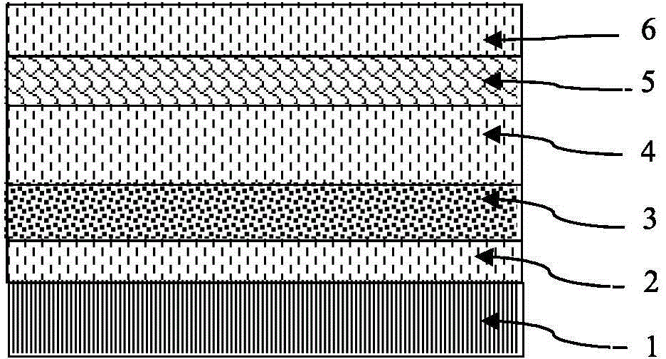
[0039] Such as figure 1 As shown, the inverted organic solar cell structure in this embodiment includes a transparent conductive film 1 , a modification layer 2 , an electron transport layer 3 , an organic light absorption layer 4 , a hole transport layer 5 and an anode electrode 6 from bottom to top. A single specific material is given in this embodiment, which does not limit the choice of other materials, but is just an example to illustrate the present invention. The ITO conductive film 1 is ultrasonically cleaned with detergent, water, isopropanol and acetone, and after drying, a 1nm LiF modification layer 2 is evaporated in vacuum, and then a 30nm ZnO electron transport layer 3 is spin-coated on the solution, and annealed at 140 degrees. , followed by spin-coating PTB7-Th:PC70BM (ratio 1:1.5) mixed organic photoactive layer 4, followed by vacuum thermal evaporation of 7nm MoO 3 A hole transport layer 5 and a silver electrode 6 of 100 nm. The efficiency of organic solar ...
Embodiment 2
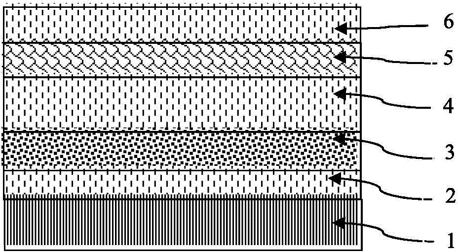
[0041] Such as figure 2 As shown, the structure of the perovskite battery in this embodiment includes a transparent conductive film 1, a modification layer 2, an electron transport layer 3, a perovskite light absorption layer 4, a hole transport layer 5 and an anode electrode 6 from bottom to top. A single specific material is given in this embodiment, which does not limit the choice of other materials, but is just an example to illustrate the present invention. The ITO conductive film 1 is ultrasonically cleaned with detergent, deionized water, isopropanol and acetone, dried, and then a 1nm LiF modification layer 2 is evaporated in vacuum, followed by a 15nm ZnO electron transport layer 3 deposited by magnetron sputtering, and then spun painted CH 3 NH 3 PB 3 The perovskite photoactive layer 4 is annealed at 60°C, then spin-coated with a Spiro-OMeTAD hole transport layer 5, and then coated with a 100nm silver electrode 6 by vacuum thermal evaporation. The perovskite batt...
Embodiment 3
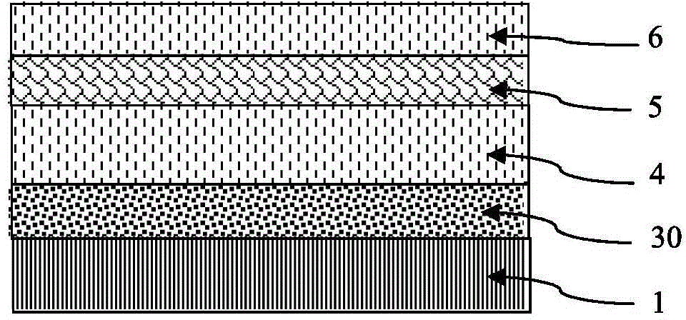
[0043] Such as image 3 As shown, in this embodiment, the inverted organic solar cell structure includes, from bottom to top, a transparent conductive film 1, a doped electron transport layer 30, an organic light absorption layer 4, a hole transport layer 5 and a silver electrode 6 (anode) . A single specific material is given in this embodiment, which does not limit the choice of other materials, but is just an example to illustrate the present invention. The ITO conductive film 1 is ultrasonically cleaned with detergent, water, isopropanol and acetone. After drying, spin-coat the doped ZnO electron transport layer 3 containing 1% LiF, and then spin-coat PTB7-Th: PC70BM (ratio 1: 1.5) Mixed photoactive layer 4, followed by vacuum thermal evaporation of 5 nm of MoO 3 A hole transport layer 5 and a silver electrode 6 of 100 nm. The efficiency of the organic solar cell adopting this structure can reach more than 10%, and the cell efficiency is basically equal to that of the c...
PUM
| Property | Measurement | Unit |
|---|---|---|
| Thickness | aaaaa | aaaaa |
| Thickness | aaaaa | aaaaa |
Abstract
Description
Claims
Application Information