Detinning and degumming equipment for printed circuit boards and electronic elements and method of detinning and degumming equipment

A technology for printed circuit boards and electronic components, applied in the field of auxiliary equipment, can solve the problems of high scrap rate of circuit boards, poor copper alloy effect, uneven repair quality, etc., so as to improve the quality of repair processing and the efficiency of tin and glue removal. High, significant absorption effect

Active Publication Date: 2015-06-10
深圳市新迪精密科技有限公司
View PDF7 Cites 18 Cited by
  • Summary
  • Abstract
  • Description
  • Claims
  • Application Information

AI Technical Summary

Problems solved by technology

[0004] 1. Use nitric acid aqueous solution, nitric acid is a strong acid, and it is liquid, it is extremely corrosive, and has certain safety hazards for personnel operation;
[0005] 2. The iron ion source and the resistance halogen ion source are disposable consumables, which have no other function after reaction and waste resources;
[0006] 3. The equipment that can withstand the above-mentioned acid liquid must be acid-resistant;
[0008] 5. The effect of removing tin, solder, and copper alloy is poor, and the scrap rate of circuit boards is high
[0009] With the continuous development of science and technology, the current SMT surface mount technology industry adopts the me

Method used


Image

  • Detinning and degumming equipment for printed circuit boards and electronic elements and method of detinning and degumming equipment
  • Detinning and degumming equipment for printed circuit boards and electronic elements and method of detinning and degumming equipment
  • Detinning and degumming equipment for printed circuit boards and electronic elements and method of detinning and degumming equipment

Examples


Embodiment 1

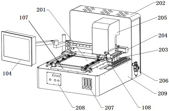
[0036] Embodiment 1: as Figure 1 to Figure 4 As shown, a printed circuit board and electronic components tin removal equipment, including a vertically placed electric box control module 202, a frame 209 vertically connected with the electric box control module 202, and a frame 209 movably connected The human-computer interaction module 104, the electric box control module 202 and the frame 209 are combined to form an L-shaped structure, the frame 209 is placed horizontally, and the workpiece bottom preheating module 107 is arranged on the frame 209, and the bottom of the workpiece The preheating module 107 is installed inside the frame 209, and is visible on the upper surface of the frame 209; on the upper surface of the frame 209, a workpiece clamping module 201 is fixed above the preheating module 107 around the bottom of the workpiece; , the electric box control module 202 is provided with a three-axis control module 115 for removing tin and glue, and the three-axis contro...

Embodiment 2

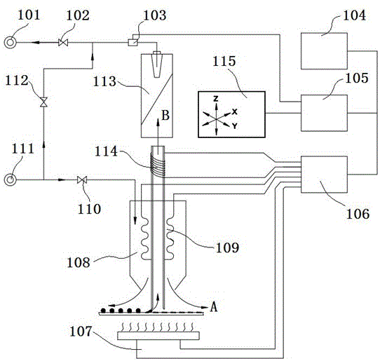
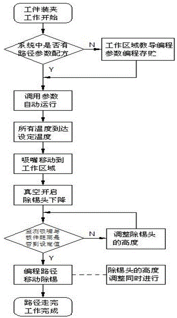
[0050] Example 2, such as Figure 5 As shown, the principle of tin removal: the workpiece (i.e. PCB board) is fixed on the workpiece clamping module 201 platform, and the preheating module 107 at the bottom of the workpiece is evenly heated to prevent PCB deformation; Nitrogen) is heated and blows to the heated pad to melt the residual tin on the surface; turn on the vacuum pump 101, open the vacuum solenoid valve 102, the pressure in the recovery pipe decreases, the suction nozzle hole in the mouth sucks in external air, and simultaneously The molten tin is sucked away. This non-contact tin removal method greatly protects the safety of the pad. Drill and embed a thermal couple (center) at the bottom of the area where tin removal is required to ensure the accuracy of the temperature of the thermocouple during the heating process. The embedded thermocouple must be fixed with high-temperature red glue.

Embodiment 3

[0051] Embodiment 3, the three-axis control module 115 of the tin and glue removal head of the present invention has four kinds of motion control modes, which are encircling and inward motion modes ( Image 6 ), lateral movement mode ( Figure 7 ), vertical movement mode ( Figure 8 ), irregular movement patterns ( Figure 9 ).

[0052] When setting the enclosing inward, horizontal movement, and vertical movement coordinates, only need to set the diagonal coordinates in the tin removal area. Coordinate setting method: such as Figure 6 to Figure 8 As shown, manually move the X-axis moving module 203 and Y-axis moving module 204 to point 1 and click "Add current coordinate value", and then move the X-axis moving module 203 and Y-axis moving module 204 to point 2 and click "Append current coordinate value". After the coordinates are set, select the appropriate path according to the type of BGA pad and generate the coordinates. When there are multiple paths for tin removal, ...


PUM


Abstract

The invention relates to auxiliary equipment used in repair of printed circuit boards (PCBs) and electronic elements, in particular to detinning and degumming equipment for the printed circuit boards and the electronic elements as well as a use method of the detinning and degumming equipment. According to the equipment, manual operation is directly replaced and accurate motion control is adopted, so that the repair processing quality of a product is greatly improved; accurate temperature control is adopted, so that the elements are prevented from being overheated and the product safety is guaranteed; vacuum adsorption is adopted during detinning and a suction nozzle is not contacted with a workpiece, so that a welding plate is prevented from falling off; the combination of a complete system enables the whole processing batch quality to be unified; the equipment is suitable for repair of PCBs and BGA (ball grid array) elements of various electronic products from low end to high end. A tin suction pipe heater assembly is further arranged at an upper part of a detinning and degumming head, so that after tin or gum is sucked, blockage of a pipeline caused by re-solidification of tin due to cooling is prevented; the heating temperature is higher than the melting point of tin, so that tin is always in a molten state. A man-machine interaction module is connected with the equipment, so that man-machine interface operation is realized and the equipment is started for automatic operation after parameter setting.

Description

[0001] technical field [0002] The invention relates to auxiliary equipment used in the maintenance of printed circuit boards and electronic components, in particular to a device for removing tin and glue from printed circuit boards and electronic components and a method for using the device. Background technique [0003] For example, the publication number is CN1214610A patent, the application date is 1998.9.29, a composition and method for removing tin and solder on the copper substrate of a printed circuit board and the tin-copper alloy under it. An aqueous solution of nitric acid to dissolve tin and solder, a source of iron ions in an amount sufficient to dissolve the tin-copper alloy, a source of halide ions in an amount sufficient to significantly increase the resistance between printed circuits go through a series of dissolving tin, solder, copper alloys, etc. on the circuit board, To achieve the purpose of removing tin, solder, copper alloy, etc. on the circuit ...

Claims


Application Information

Patent Timeline
IPC IPC(8): B23K1/018
CPCB23K1/018B23K2101/42
Inventor 彭其鸿戴俊
Owner 深圳市新迪精密科技有限公司
Why Eureka
Try Eureka