Equipment and method for removing tin and glue from printed circuit boards and electronic components
A technology for printed circuit boards and electronic components, applied in the field of auxiliary equipment, can solve the problems of high scrap rate of circuit boards, overheating of pads, circuit burnout, poor copper alloy effect, etc. Safe and effective absorption
- Summary
- Abstract
- Description
- Claims
- Application Information
AI Technical Summary
Problems solved by technology
Method used
Image
Examples
Embodiment 1
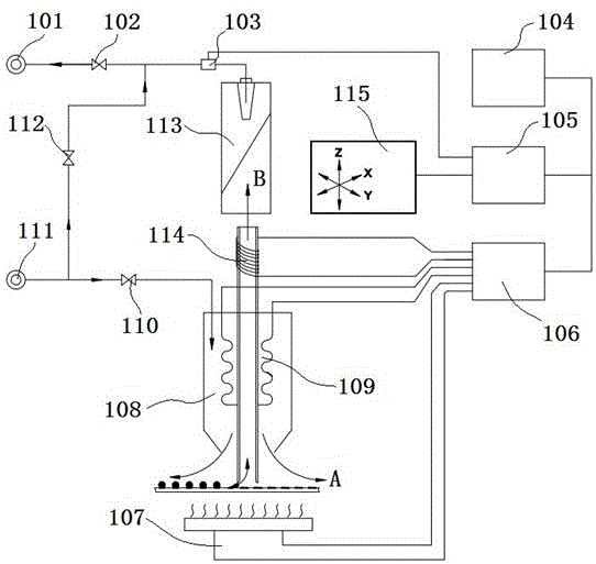
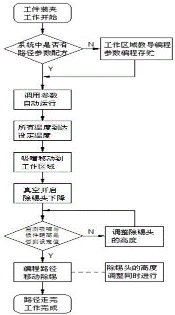
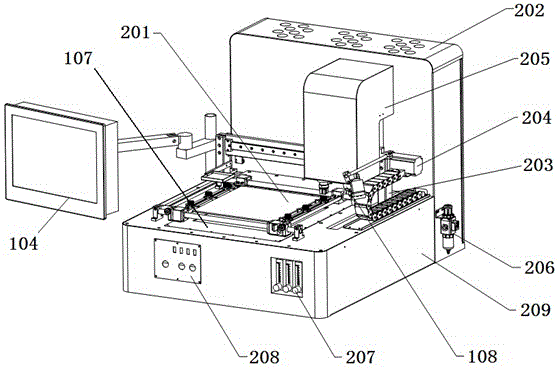
[0035] Embodiment 1: as Figure 1 to Figure 4 As shown, a printed circuit board and electronic components tin removal equipment, including a vertically placed electric box control module 202, a frame 209 vertically connected with the electric box control module 202, and a frame 209 movably connected The human-computer interaction module 104, the electric box control module 202 and the frame 209 are combined to form an L-shaped structure, the frame 209 is placed horizontally, and the workpiece bottom preheating module 107 is arranged on the frame 209, and the bottom of the workpiece The preheating module 107 is installed inside the frame 209, and is visible on the upper surface of the frame 209; on the upper surface of the frame 209, a workpiece clamping module 201 is fixed above the preheating module 107 around the bottom of the workpiece; , the electric box control module 202 is provided with a three-axis control module 115 for removing tin and glue, and the three-axis contro...
Embodiment 2
[0049] Example 2, such as Figure 5 As shown, the principle of tin removal: the workpiece (i.e. PCB board) is fixed on the workpiece clamping module 201 platform, and the preheating module 107 at the bottom of the workpiece is evenly heated to prevent PCB deformation; It is nitrogen) and blows to the heated pad after heating to melt the residual tin on the surface; turn on the vacuum pump 101, open the vacuum solenoid valve 102, the pressure in the recovery pipe decreases, and the suction nozzle hole of the mouth sucks the external air, and simultaneously The molten tin is sucked away. This non-contact tin removal method greatly protects the safety of the pad. Drill and embed a thermal couple (center) at the bottom of the area where tin removal is required to ensure the accuracy of the temperature of the thermocouple during the heating process. The embedded thermocouple needs to be fixed with high-temperature red glue.
Embodiment 3
[0050] Embodiment 3, the three-axis control module 115 of the tin and glue removal head of the present invention has four kinds of motion control modes, which are encircling and inward motion modes ( Image 6 ), lateral movement mode ( Figure 7 ), vertical movement mode ( Figure 8 ), irregular movement patterns ( Figure 9 ).
[0051] When setting the enclosing inward, horizontal movement, and vertical movement coordinates, only need to set the diagonal coordinates in the tin removal area. Coordinate setting method: such as Figure 6 to Figure 8 As shown, manually move the X-axis moving module 203 and Y-axis moving module 204 to point 1 and click "Add current coordinate value", and then move the X-axis moving module 203 and Y-axis moving module 204 to point 2 and click "Append current coordinate value". After the coordinates are set, select the appropriate path according to the type of BGA pad and generate the coordinates. When there are multiple paths for tin removal, ...
PUM
 Abstract
Description
Claims
Application Information
 - R&D
- Intellectual Property
- Life Sciences
- Materials
- Tech Scout
- Unparalleled Data Quality
- Higher Quality Content
- 60% Fewer Hallucinations
Browse by: Latest US Patents, China's latest patents, Technical Efficacy Thesaurus, Application Domain, Technology Topic, Popular Technical Reports.
© 2025 PatSnap. All rights reserved.Legal|Privacy policy|Modern Slavery Act Transparency Statement|Sitemap|About US| Contact US: help@patsnap.com


