Preparation method of curved-surface fly's-eye lens array

A technology of lens array and microlens array, which is applied in the field of optical bionics, can solve the problems of device sealing, complicated process, complex process, etc., and achieve the effect of low price, simple preparation process and good toughness

A technology of lens array and microlens array, which is applied in the field of optical bionics, can solve the problems of device sealing, complicated process, complex process, etc., and achieve the effect of low price, simple preparation process and good toughness

CN104698516AInactive Publication Date: 2015-06-10LANZHOU UNIVERSITY

Image

  • Preparation method of curved-surface fly's-eye lens array
  • Preparation method of curved-surface fly's-eye lens array
  • Preparation method of curved-surface fly's-eye lens array

Examples


Embodiment

[0026] A method for preparing a curved surface bionic fly-eye lens array by magnetic field induction, the specific process is:

[0027] In this example, the mass fraction of carbonyl iron powder inclusions was chosen to be 70% for the preparation of the magnetoelastic film, mainly because when the volume fraction of inclusions is low, the force of the magnetoelastic film and the external magnetic field after magnetization is small, and the deformation produced is relatively small. Small; when the inclusion volume fraction is higher, the bending stiffness of the magnetoelastic film increases and it is not easy to deform.

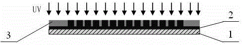
[0028] Spin-coat SU8 or other photoresists on other substrates 1 such as silicon or glass;

[0029] Use a mask to expose it to ultraviolet light for 3 engravings, and after development, a series of cylindrical structures with a diameter of 10 μm are formed, such as figure 1 shown.

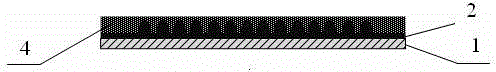
[0030] Put the cylinder in an oven at 160°C and bake for 20 minutes. Under...


PUM


Abstract

The invention discloses a preparation method of a curved-surface fly's-eye lens array. According to the advantages of big deformation behavior of a flexible film mixed up with ferromagnetic grains in a magnetic field environment, and deflection controlled by the magnetic field, the preparation method of the curved-surface fly's-eye lens array through the induction of the magnetic field is proposed; from the manufacturing technique, the preparation method is featured by fast and simple operation, low cost and small dimension of a single lens, and so on.

Description

technical field [0001] The invention relates to the field of optical bionic technology, in particular to a method for preparing a curved surface bionic fly-eye lens array. Background technique [0002] Biological compound eyes are composed of a group of "small eyes" gathered together. They have the advantages of small size, large field of view, high sensitivity, and speed measurement. And civil industry has broad application prospects. At present, according to the structure and imaging principle of biological compound eyes, scientists have produced many bionic curved surface compound eye microlenses with optical systems. The difficulty in manufacturing bionic fly-eye lenses lies in how to realize the manufacture of curved surface microlens arrays and the size of a single lens below the millimeter level, so as to realize the large field of view and high-resolution three-dimensional complex imaging of the fly-eye lens. [0003] He et al. used glass bead punching to assist in...

Claims


Application Information

Patent Timeline
10 Jun 2015
Publication
CN104698516A
IPC
G02B3/00; G02B1/14
CPC
G02B3/0012
Inventors
高伟; 王兰兰