
Liquid static pressure guide rail oil film thickness control system and method based on oil temperature compensation

A technology of hydrostatic guideway and oil film thickness, which is applied in the direction of manufacturing tools, other manufacturing equipment/tools, large fixed members, etc. It can solve the problems of not considering the change of oil temperature and low control accuracy, so as to overcome the drop of oil pressure, The effect of high control precision and fast response

Inactive Publication Date: 2015-07-15
ANHUI UNIVERSITY OF TECHNOLOGY AND SCIENCE
View PDF8 Cites 11 Cited by
  • Summary
  • Abstract
  • Description
  • Claims
  • Application Information

AI Technical Summary

Problems solved by technology

In the Chinese patent application number 201410196676.2 of a machine tool open hydrostatic guideway oil film thickness control device and system and the patent application number 201010570464.8 of the device and method for frequency conversion control of guide rail oil film thickness, it is proposed that the main control system uses frequency converter plus asynchronous The closed loop composed of the motor controls the oil film thickness of the guide rail, but there are deficiencies in the control accuracy is not high and the oil temperature change is not considered
In the Chinese patent application number 201410196676.2, a machine tool open hydrostatic guideway oil film thickness control device and the oil return circuit of the system use a throttle valve to control the oil return speed and protect the oil circuit, and the control accuracy is not high.

Method used


Image

  • Liquid static pressure guide rail oil film thickness control system and method based on oil temperature compensation
  • Liquid static pressure guide rail oil film thickness control system and method based on oil temperature compensation
  • Liquid static pressure guide rail oil film thickness control system and method based on oil temperature compensation

Examples


Embodiment Construction

[0011] Referring to the accompanying drawings, through the description of the embodiments, the specific embodiments of the present invention include the shape, structure, mutual position and connection relationship of each part, the function and working principle of each part, and the manufacturing process of the various components involved. And the method of operation and use, etc., are described in further detail to help those skilled in the art have a more complete, accurate and in-depth understanding of the inventive concepts and technical solutions of the present invention.

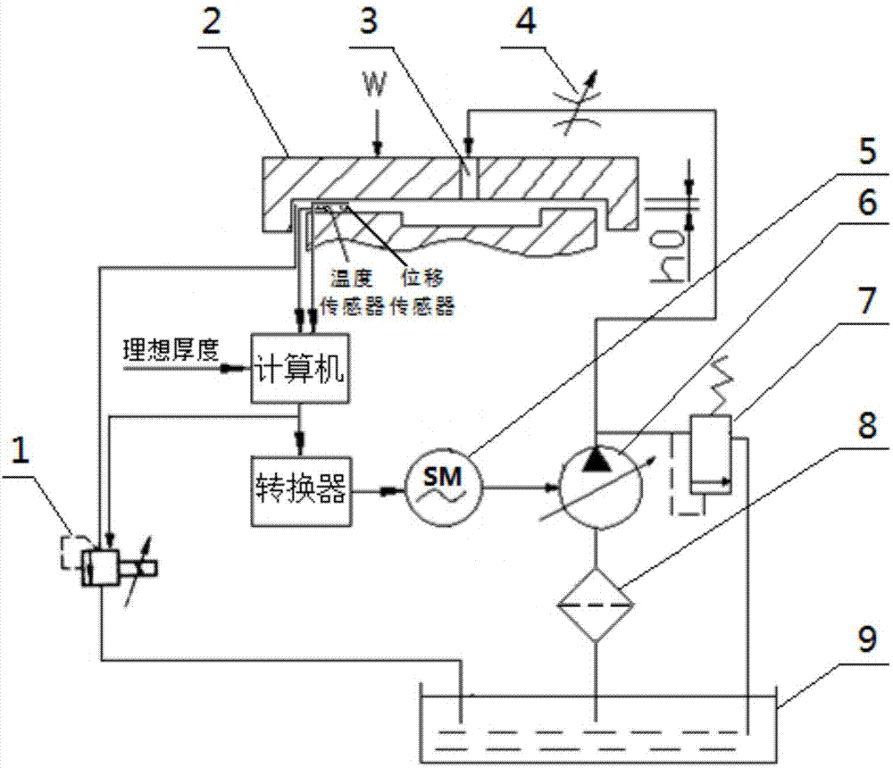
[0012] A hydrostatic guide rail oil film thickness control system based on oil temperature compensation, the device includes a control unit, a throttle valve 34, a guide rail 2, a displacement sensor for detecting the thickness of the oil film, a variable pump 6 for supplying oil to the guide rail 2, a drive The AC servo motor 5 of the variable pump 6, the proportional relief valve 1 for controlling t...


PUM


Abstract

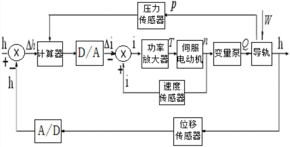
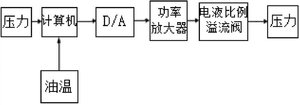
The invention provides a liquid static pressure guide rail oil film thickness control system and method based on oil temperature compensation. According to the method, a flow rate equation between guide rails is built; the flow rate equation is subjected to linearization; a guide rail stress equation is built; then, the linearized flow rate equation and the guide rail stress equation are subjected to Laplace transformation, so that an oil film thickness response load mechanism is obtained. For the oil film thickness control, the set oil film thickness is compared with the actual oil film thickness detected by a sensor, a difference value signal is subjected to control algorithm calculation, then, through signal conversion and power amplification, a simulation signal is obtained; the simulation signal is used for controlling an alternating servo motor and a proportional overflow valve, and the alternating current servo motor drives a variable pump, so that the oil flow rate of oil liquid outputted by the variable pump adapts to the flow rate required between movable and fixed guide rails, meanwhile, when the oil temperature changes, the pressure of the proportional overflow valve is controlled by a computer, and the change of the static pressure guide rail oil liquid pressure due to temperature change is compensated.

Description

technical field [0001] The invention relates to the field of hydrostatic guide rails for machine tools, in particular to a method for establishing a load response mechanism for oil film thickness of hydrostatic guide rails with oil temperature compensation, and in particular to a control system for oil film thickness of hydrostatic guide rails based on oil temperature compensation and methods. Background technique [0002] Due to the advantages of long working life, low friction coefficient, small influence of speed change and load change on oil film stiffness, and stable operation, hydrostatic guide rails are widely used in precision machining machine tools, radar antennas and other civil and military equipment. With the continuous improvement of the machining accuracy and efficiency requirements of CNC machine tools, in order to improve the bearing capacity and performance of the workbench, reduce the wear between the workbench and the base, and prolong the service life of...

Claims


Application Information

Patent Timeline
IPC IPC(8): B23Q17/00B23Q1/01
CPCB23Q1/38B23Q23/00
Inventor 王幼民徐彬雪李龙蔡志成
Owner ANHUI UNIVERSITY OF TECHNOLOGY AND SCIENCE
Learn More