Optical film with adhesive on both sides and method for fabrication of image display device employing same
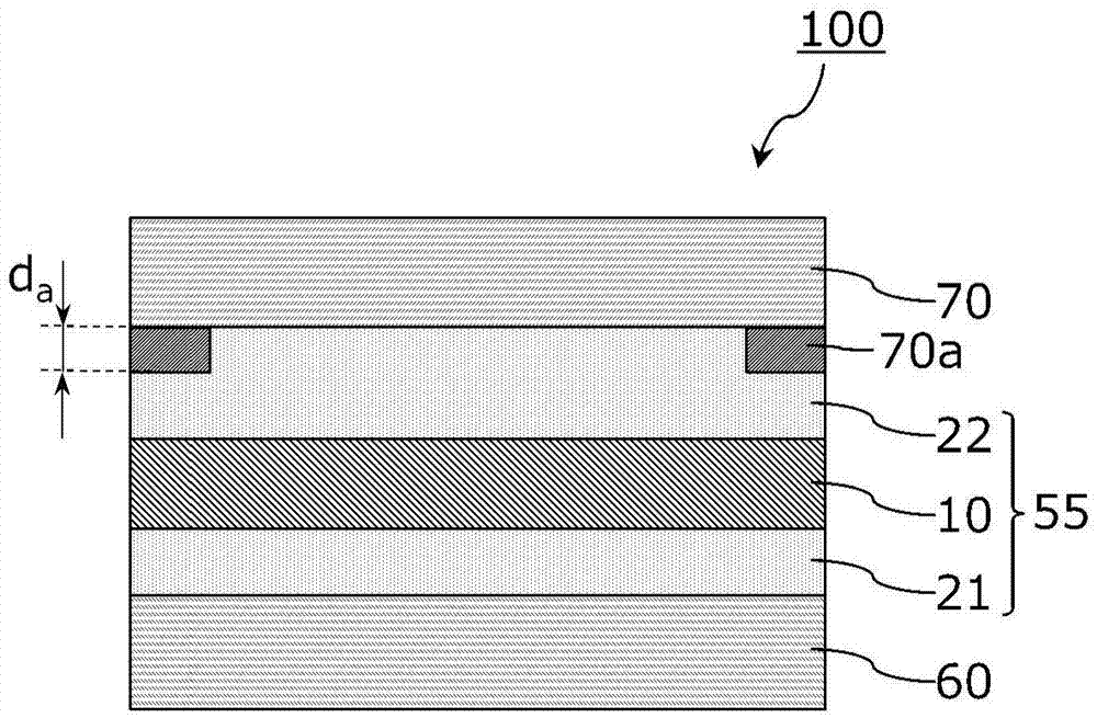
An image display device, optical film technology, applied in the direction of adhesive types, chemical instruments and methods, ester copolymer adhesives, etc., can solve the problem of reducing the visibility of the image display device, increasing the reflection or refraction at the interface, etc. problems, and achieve the effects of suppressing the positional deviation of components or the protrusion of adhesive, suppressing the generation of air bubbles, and simplifying the manufacturing process.
- Summary
- Abstract
- Description
- Claims
- Application Information
AI Technical Summary
Problems solved by technology
Method used
Image
Examples
Embodiment 1
[0135]
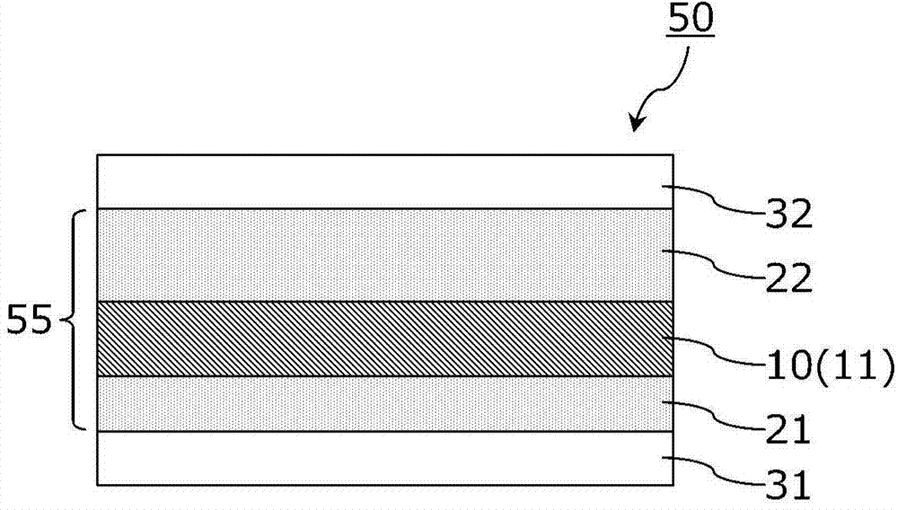
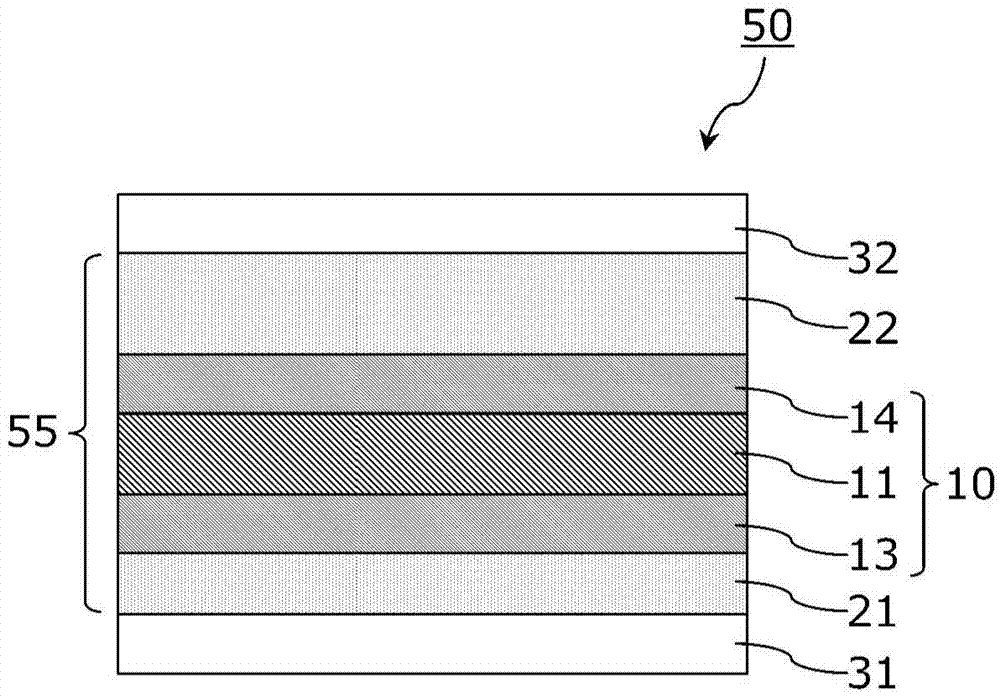
[0136] A polarizing plate (degree of polarization: 99.995%) was used in which a polarizer made of a stretched polyvinyl alcohol film impregnated with iodine and having a thickness of 25 μm was bonded to both sides of a polarizer. The transparent protective film on one side of the polarizer (image display unit side) is a retardation film containing a triacetyl cellulose film with a thickness of 40 μm, and the transparent protective film on the other side (visible side) is a triacetyl cellulose with a thickness of 60 μm film.
[0137]
[0138] (Preparation of Base Polymer)
[0139] In a detachable flask equipped with a thermometer, a stirrer, a reflux condenser, and a nitrogen inlet tube, put 97 parts of butyl acrylate, 3 parts of acrylic acid, 0.2 parts of azobisisobutyronitrile as a polymerization initiator, and 233 parts of ethyl acetate ester, and then nitrogen gas was introduced, and nitrogen replacement was carried out for about 1 hour while stirring. Then, ...
Embodiment 2、3
[0160] An adhesive composition (solution) having the composition shown in Table 1 was prepared as the visible side adhesive layer B. As a tackifier, a styrene oligomer ("YS Resin SX-85" manufactured by Yasuhara Chemical Co., Ltd., softening point 85°C) was used in Example 2, and a nuclear hydrogenated terpene phenol (Yasuhara Chemical Co., Ltd.) was used in Example 3. "YS Polyster NH" manufactured by Kagaku Co., Ltd., softening point: 130°C). In addition, the adhesives of Examples 2 and 3 contain phenyl glycidyl ether acrylate ("New Frontier PGA" manufactured by Daiichi Kogyo Pharmaceutical Co., Ltd.) as a photopolymerizable acrylic monomer, and contain 1-hydroxyl Cyclohexyl phenyl ketone ("Irgacure 184" manufactured by Ciba Specialty Chemicals) was used as a photo-curable adhesive as a photo radical generator.
[0161] A polarizing plate with an adhesive on both sides was produced in the same manner as in Example 1 except that a photocurable adhesive layer having the composi...
Embodiment 4~6
[0163] (Preparation of Base Polymer)
[0164] In a detachable flask with a thermometer, a stirrer, a reflux condenser and a nitrogen inlet tube, put 75 parts by weight of 2-ethylhexyl acrylate (2EHA), 25 parts of hydroxyethyl acrylate (HEA), 0.2 parts as a polymerization Azobisisobutyronitrile and 233 parts by weight of ethyl acetate were used as initiators, and then nitrogen gas was introduced, and nitrogen replacement was performed for about 1 hour while stirring. Then, the flask was heated to 70° C. and reacted for 5 hours to obtain an acrylic polymer having a weight average molecular weight (Mw) of 700,000 (hereinafter, this base polymer is referred to as “polymer 2”).
[0165]
[0166]Using the above polymer 2, adhesive compositions (solutions) having the compositions shown in Table 1 were prepared. A double-sided adhesive-attached polarizing plate was produced in the same manner as in Example 1 except that an adhesive layer having the composition and thickness shown i...
PUM
| Property | Measurement | Unit |
|---|---|---|
| thickness | aaaaa | aaaaa |
| thickness | aaaaa | aaaaa |
| softening point | aaaaa | aaaaa |
Abstract
Description
Claims
Application Information
 - R&D
- Intellectual Property
- Life Sciences
- Materials
- Tech Scout
- Unparalleled Data Quality
- Higher Quality Content
- 60% Fewer Hallucinations
Browse by: Latest US Patents, China's latest patents, Technical Efficacy Thesaurus, Application Domain, Technology Topic, Popular Technical Reports.
© 2025 PatSnap. All rights reserved.Legal|Privacy policy|Modern Slavery Act Transparency Statement|Sitemap|About US| Contact US: help@patsnap.com


