Double-tower catalysis thermal-coupling reflux deamination method and deamination device thereof

A heat coupling and deamination technology, applied in the field of deamination treatment, can solve the problems of high cost of treatment chemicals, harsh requirements for pretreatment water, high investment, etc., achieve remarkable environmental and social benefits, solve the problem of standard discharge, and overcome the problem of liquid spraying. The effect of a large amount of showering

Active Publication Date: 2015-08-26
JIANGXI NAIKE CHEM IND EQUIP PACKINGCO
View PDF10 Cites 5 Cited by
  • Summary
  • Abstract
  • Description
  • Claims
  • Application Information

AI Technical Summary

Problems solved by technology

[0010] 1) The continuous A / O method not only has high investment, but also occupies a large area, and has strict requirements on the pretreatment effluent (such as NH3-N must be less than 200mg / l, and the stripping or stripping method is suitable for high concentration of more than 2000mg / l) Ammonia nitrogen wastewater cannot meet this requirement at all, and can only be diluted with doubled water before treatment)
[0011] 2) Although the investment and floor area of ​​the continuous chemical precipitation method are smaller than the A / O method, the consumption of chemicals is too large. The ratio of N:P:Mg is 1:1.1-1.2, and the cost of treating chemicals is too high. Moreover, the effluent cannot meet the national primary or secondary discharge standards.
[0012] 3) In the current ammonia stripping treatment process, the stripping efficiency of ammonia nitrogen can only reach 85-90%, and ammonia stripping enters the atmosphere to cause secondary pollution

Method used


Image

  • Double-tower catalysis thermal-coupling reflux deamination method and deamination device thereof

Examples


Embodiment Construction

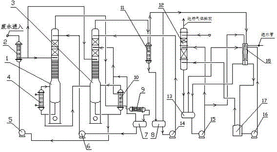
[0028] a. Add a pH regulator (equivalently a neutralizer, such as hydrochloric acid, sodium hydroxide, potassium hydroxide, sodium carbonate and ammonia water, etc.) and a compound ammonia solution agent (such as ammonia water and liquid chlorine, etc.) into the ammonia nitrogen wastewater buffer pool , add 60g~80g compound ammonia solution agent to one cubic meter of wastewater to adjust the pH value of ammonia nitrogen wastewater to 10.5~11.5;

[0029] b. Preheat the ammonia nitrogen wastewater treated in step a to 40-50°C through the wastewater preheater,

[0030] c. A part of the ammonia nitrogen waste water preheated in step b is sent to the middle section of the hot pressurized tower to fully contact with the hot steam rising in the hot pressurized tower produced by the reboiler. The pressure of the heated steam is 0.6Mpa, and then The ammonia-containing vapor generated at the top of the hot pressurized tower is sent to the reboiler of the coupled low-pressure column for...


PUM


Abstract

The invention discloses a double-tower catalysis thermal-coupling reflux deamination method. The method comprises steps as follows: a pH conditioner and a composite deamination agent are added to an ammonia-nitrogen wastewater buffer pool, the mixture is preheated, one part of preheated ammonia-nitrogen wastewater is sent into a middle section of a thermal pressurizing tower to be fully contacted with hot steam which is produced by a reboiler and rises in the thermal pressurizing tower, ammonia-containing steam produced at the top of the thermal pressurizing tower is sent into a reboiler of a low-pressure coupling tower for condensation and rectification, then the ammonia-containing steam is sent into the lower part of the low-pressure coupling tower for rectification, and deaminated wastewater produced at the bottom of the thermal pressurizing tower is sent into the bottom in the low-pressure coupling tower; meanwhile, the other part of the preheated ammonia-nitrogen wastewater is sent into a middle section of the low-pressure coupling tower to be fully contacted with the ammonia-containing steam, and ammonia-containing steam is produced at the top of the low-pressure coupling tower. The NH3-N index of the deaminated wastewater can reach the national first-class discharge standard (15 ppm), industrial ammonia water with high quality can be recovered, energy consumption is greatly reduced, and compared with conventional distillation technologies, the method has the advantages that the energy-saving efficiency is higher than 40% and economic benefit and social benefit are very significant.

Description

technical field [0001] The invention relates to a deammonization treatment method, in particular to a double-tower catalytic thermal coupling countercurrent deammonization method and a deammonization device. Background technique [0002] At present, methods such as air stripping, breakpoint chlorination and MAP chemical precipitation are mainly used for the treatment of high-concentration ammonia-nitrogen wastewater. The stripping method has simple process, stable effect and low investment; but it consumes a lot of energy and causes secondary pollution. The treatment effect of the breakpoint chlorination method is stable and is not affected by the water temperature; however, the operating cost is high, and the by-products of chloramines and chlorinated organic compounds will cause secondary pollution. Although the chemical precipitation method can better remove ammonia nitrogen and realize resource recovery, the main limitation of this method is that the amount of precipita...

Claims


Application Information

Patent Timeline
Patent Type & Authority Applications(China)
IPC IPC(8): C02F9/10
Inventor 赖祖明韩博平赖兴
Owner JIANGXI NAIKE CHEM IND EQUIP PACKINGCO
Why Eureka
Try Eureka