Atmospheric and vacuum catalytic flue gas-oil slurry heat combined device

A technology for catalyzing flue gas and a combined device, which is applied in the petroleum industry, processing hydrocarbon oil, etc., can solve the problems of reducing economic benefits, reducing the power of the hood, increasing the back pressure of the hood, and solving the problems of low heat utilization rate and structural Reasonable design and the effect of improving economical effect

Active Publication Date: 2015-09-23
雷泽永
View PDF6 Cites 2 Cited by
  • Summary
  • Abstract
  • Description
  • Claims
  • Application Information

AI Technical Summary

Problems solved by technology

At present, domestic refinery catalytic high-temperature waste heat is all used as boiler to produce medium-pressure steam. For example, a refinery with 3 million tons of catalytic waste heat produces 100 tons / hour of medium-pressure steam, and the refinery power station is a high-pressure coal-fired power station. steam boiler, therefore, the use efficiency of catalytic waste heat is only equivalent to that of coal
In addition, the catalytic waste boiler also needs to use a large amount of gas (about 30-50%) to supplement heat, which undoubtedly turns gas into coal, which also reduces economic benefits
[0011] 2. The thermal energy utilization efficiency of the catalytic waste heat boiler is low
[0014] 2. Catalytic waste heat boilers are all small boilers with low thermal efficiency, only about 85%, about 8% lower than high-pressure boilers (such as CFB boiler thermal efficiency 93%)
[0015] 3. Security issues
[0018] 1. Incomplete utilization of the waste heat of the catalytic device: There are three pieces of waste heat used by the catalytic device to produce medium-pressure steam: the first piece is the waste heat of flue gas, accounting for about 40%; the second piece is the waste heat of oil slurry, accounting for about 50%; the third piece is The block is about 10% of the waste heat in the second medium
The first patent application only covers the utilization of catalytic flue gas waste heat, but does not include the second and third waste heat utilization, but it has created conditions for the second and third waste heat utilization
[0019] 2. Put the waste heat of the flue gas in the heating furnace of the atmospheric and vacuum device, which affects the energy-saving efficiency of the catalytic device: the first patent application puts the waste heat of the flue gas in the heating furnace of the atmospheric and vacuum device. The heating furnace of the pressure device is 100-200 meters apart, which will increase the back pressure of the hood and reduce the power of the hood by about 1000Kw, which is not good for catalytic energy saving

Method used


Image

  • Atmospheric and vacuum catalytic flue gas-oil slurry heat combined device

Examples


Embodiment Construction

[0038] The present invention will be further described in detail below in conjunction with the accompanying drawings and embodiments.

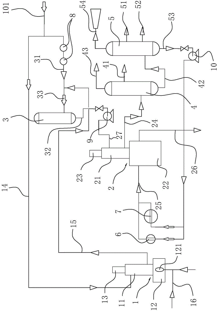
[0039] Such as figure 1 As shown, the atmospheric and vacuum device of the present embodiment, which replaces heating furnace fuel with catalytic flue gas and oil slurry waste heat, includes a first heating furnace 1, a second heating furnace 2, a flash tower 3, an aviation coal atmospheric tower 4, Diesel decompression tower 5, No. 2 heat exchanger 6 and oil slurry heat exchanger 7, wherein the first heating furnace 1 is a flue gas heating furnace, which is a pure convection tube heating furnace without a radiation chamber. The first heating furnace 1 is divided into the first convection chamber 11 and the upper and lower parts of the combustion chamber 12. The bottom of the first heating furnace 1 is provided with the flue gas pipeline 16 of the combustion chamber 12 for the catalytic flue gas to enter, and the combustion chamber 12 is provi...


PUM


Abstract

An atmospheric and vacuum device adopting catalytic flue gas and oil slurry waste heat to replace a heating furnace fuel comprises a first heating furnace, a second heating furnace, a flash evaporation tower, a jet fuel atmospheric tower and a diesel fuel vacuum tower, wherein the first heating furnace adopts a flue gas heating furnace, and a first crude oil inlet pipeline and a first crude oil outlet pipeline are arranged on the flue gas heating furnace; a second crude oil inlet main pipeline is arranged on the flash evaporation tower, and crude oil after heating by the first heating furnace and second-way crude oil enter the pipeline to be mixed; a pipeline connected with a crude oil outlet pipeline on the flash evaporation tower and a crude oil output second heating furnace pipeline are arranged on the second heating furnace; a connection port connected with the crude oil output second heating furnace pipeline is formed in the jet fuel atmospheric tower; a connection port connected with a jet fuel atmospheric tower crude oil extraction pipeline is formed in the diesel fuel vacuum tower; a heavy oil extraction pipeline is arranged at the bottom of the diesel fuel vacuum tower, and an adjusting circulating oil heat exchanger and an oil slurry heat exchanger are arranged between the heavy oil extraction pipeline and the second heating furnace. The atmospheric and vacuum device is reasonable in design, efficient and energy-saving, three waste heats including the catalytic flue gas, the oil slurry and adjusting circulating oil are sufficiently used, and the economic benefits are enhanced.

Description

technical field [0001] The invention belongs to the technical field of petroleum processing, and relates to an atmospheric and vacuum device, in particular to an atmospheric and vacuum device which uses catalytic flue gas and oil slurry waste heat to replace heating furnace fuel. Background technique [0002] Catalysis is an important production unit in a refinery. Its production process is to produce liquefied gas, gasoline, diesel gas and coke by catalytic cracking of wax oil and residual oil. Catalytic reaction, charring and distillation process produce a lot of waste heat, among which, the waste heat with high temperature (above 360°C) is composed of three parts: 1. The catalyst burnt will generate tens of thousands of cubic meters of high-temperature flue gas, medium and large catalytic The amount of flue gas discharged from the regenerator of the device is about 100,000-250,000 cubic meters per hour (3 million tons of catalytic devices, the flue gas is about 250,000 cu...

Claims


Application Information

Patent Timeline
Patent Type & Authority Applications(China)
IPC IPC(8): C10G53/00
Inventor 雷泽永
Owner 雷泽永
Why Eureka
Try Eureka