Coal-fired power plant flue gas heat regenerative system and energy-saving water-saving ultra-clean discharging method

A technology for regenerative heating systems and coal-fired power plants, which is applied in combustion methods, combustion equipment, fuel supply, etc., can solve the problems of not using low-temperature economizers to cool down, cannot separate water, and generate dust, so as to avoid corrosion of chimneys and chimneys. White smoke, which is conducive to natural lifting and diffusion, and the effect of reducing the moisture content of smoke

Active Publication Date: 2015-09-23
SHANDONG UNIV +2
View PDF10 Cites 24 Cited by
  • Summary
  • Abstract
  • Description
  • Claims
  • Application Information

AI Technical Summary

Problems solved by technology

[0006] Invention patent "A multi-stage waste heat recovery device" (application number: 201110379906.5, application date: 2011-11-25) and "deep recovery and utilization of waste heat of power plant boiler flue gas and emission reduction system" (application number: 201310534820.4, application date : 2013-11-04) only reduces the exhaust heat loss by absorbing the sensible heat of the flue gas, but does not recycle the latent heat of water vapor in the flue gas, nor achieve the purpose of saving water
[0007] Invention patent "An Economizer for Deep Recovery and Utilization of Flue Gas Waste Heat of Coal-fired Boiler and Flue Gas Condensation Desulfurization and Dust Removal" (application number: 201110260716.1, application date: 2011-09-06) provides a Economizer with latent heat of gasification. Although the technology involved in this patent utilizes the latent heat of gasification of part of the water vapor in the flue gas, the moisture in the flue gas is not separated cleanly for use, but generates dust, Aci

Method used


Image

  • Coal-fired power plant flue gas heat regenerative system and energy-saving water-saving ultra-clean discharging method

Examples


Embodiment Construction

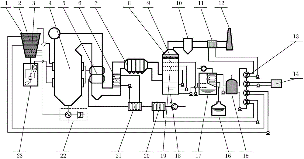
[0049] The present invention will be further described below in conjunction with the accompanying drawings and embodiments.

[0050] Such as figure 1 As shown, the present invention is based on conventional coal-fired power plant boiler furnace, burner, flue air system, air preheater, pulverizing system, coal bunker, slagging system, electrostatic precipitator, desulfurization tower, wet electrostatic precipitator , adding low-temperature economizer, first-level air heater, second-level air heater, last-stage spraying device, vacuum flash evaporation flash-condensation device, low-temperature heat pump heat exchange device, waste heat utilization heat exchanger, first-level coal drying device, Secondary coal drying unit, flue gas reheat heat exchanger, and piping and pumps or fans connecting these units. Among them, the outlet of the boiler furnace is connected to the boiler flue air system, and the output pipe behind the air preheater of the boiler flue air system is equippe...


PUM


Abstract

The invention discloses a coal-fired power plant flue gas heat regenerative system and an energy-saving water-saving ultra-clean discharging method. The temperature of the flue gas is reduced to about 90-110 DEG.C through a low-temperature coal economizer, and the recycled flue gas heat heats primary and secondary wind entering a boiler through a steam air heaters, so that the first stage of heat regenerative cycles is achieved. The temperature of the flue gas at the outlet of a desulfurization tower is reduced to 30-40 DEG.C through a vacuum flash evaporation and solidification device and a low-temperature heat pump heat exchange device, and a part of water vapor of the flue gas is condensed and collected, so that water is saved. The low-temperature heat pump heat exchange device absorbs the latent heat released in flue gas sensible heat and condensation processes, and dry as-fired coal and air are heated, so that the second stage of heat regenerative cycles is achieved. A boiler slag discharge system recycles the waste heat of heat slag, and the as-fired coal is heated, so that the third stage of heat regenerative cycles is achieved. When the waste heat is not used up, the remained waste heat can be utilized, so that energy is saved. Low-temperature desulphurization slurry led out from the vacuum flash evaporation and solidification device is injected into the desulfurization tower, so that the desulphurization efficiency is improved, and an ultra-clean discharging objective is achieved.

Description

technical field [0001] The invention relates to a flue gas recovery system of a coal-fired power plant and an energy-saving, water-saving and ultra-clean discharge method. Background technique [0002] Coal-fired power plants consume a lot of energy, SO 2 The emission of pollutants will pollute the environment. Coal is gradually decreasing as a non-renewable energy source, and the problem of air pollution is becoming increasingly serious. In this context, power plants are required to continuously tap the energy-saving potential and increase the intensity of pollutant control. [0003] The exhaust heat loss accounts for a large proportion of the energy loss of coal-fired power plants, so reducing the exhaust heat loss has become one of the technical directions for energy conservation in coal-fired power plants, but most of the flue gas waste heat utilization technologies currently only absorb the flue gas sensible heat. To reduce the heat loss of exhaust fume, due to the l...

Claims


Application Information

Patent Timeline
IPC IPC(8): F23L15/00F23K1/04F23J15/04
CPCY02E20/34
Inventor 马春元李玉忠张立强陈桂芳崔琳常景彩杜谦高秀丽刘晓高建民
Owner SHANDONG UNIV
Why Eureka
Try Eureka