Manufacturing method of customized tongue-side invisible aligner

A technology for invisible orthodontics and manufacturing method, applied in the field of orthodontics, can solve the problems of large bonding area of ​​the bottom plate, insufficient elasticity, poor bonding strength, etc., achieve good safety and stability, reduce gingival inflammation, and reduce the possibility of Effect

Inactive Publication Date: 2015-10-14
JINHUA KEDIFU MEDICAL TECH CO LTD
View PDF6 Cites 9 Cited by
  • Summary
  • Abstract
  • Description
  • Claims
  • Application Information

AI Technical Summary

Problems solved by technology

However, their manufacturing brackets all adopt traditional casting technology, and the precision and cohesion of the brackets produced are poor, and the accuracy can only reach 0.05 mm at most, because the lingual brackets of the aligner are placed in a fan-shaped radial bonding On the lingual side of the teeth, three sequences of bending of the tooth position need to be placed in the bracket, and the particularity of the bonding position of the lingual bracket makes the precision requirement of the lingual bracket higher than that of the general labial bracket, for example, When the missing angle of the common labial bracket is 1 degree, the missing angle of the tooth angle is less than 1°, and the radial angle of the lingual bracket may be lost by 2°. Therefore, the accuracy of the precision casting process is only 0.05-0.80MM, which is difficult to meet the lingual bracket. At the same time, Guangzhou Ruitong Biotechnology Co., Ltd. and 3M Company of the United States designed the bonding base plate of the orthodontic bracket to simulate the overall base plate of the mesh. Although the bonding area of ​​the base plate designed in this way is large, the bonding strength Poor, and due to the large bonding area of ​​the bottom plate, it is easy to contact and rub against the gums, causing inflammation of the gums
Amon

Method used


Image

  • Manufacturing method of customized tongue-side invisible aligner
  • Manufacturing method of customized tongue-side invisible aligner
  • Manufacturing method of customized tongue-side invisible aligner

Examples


Embodiment Construction

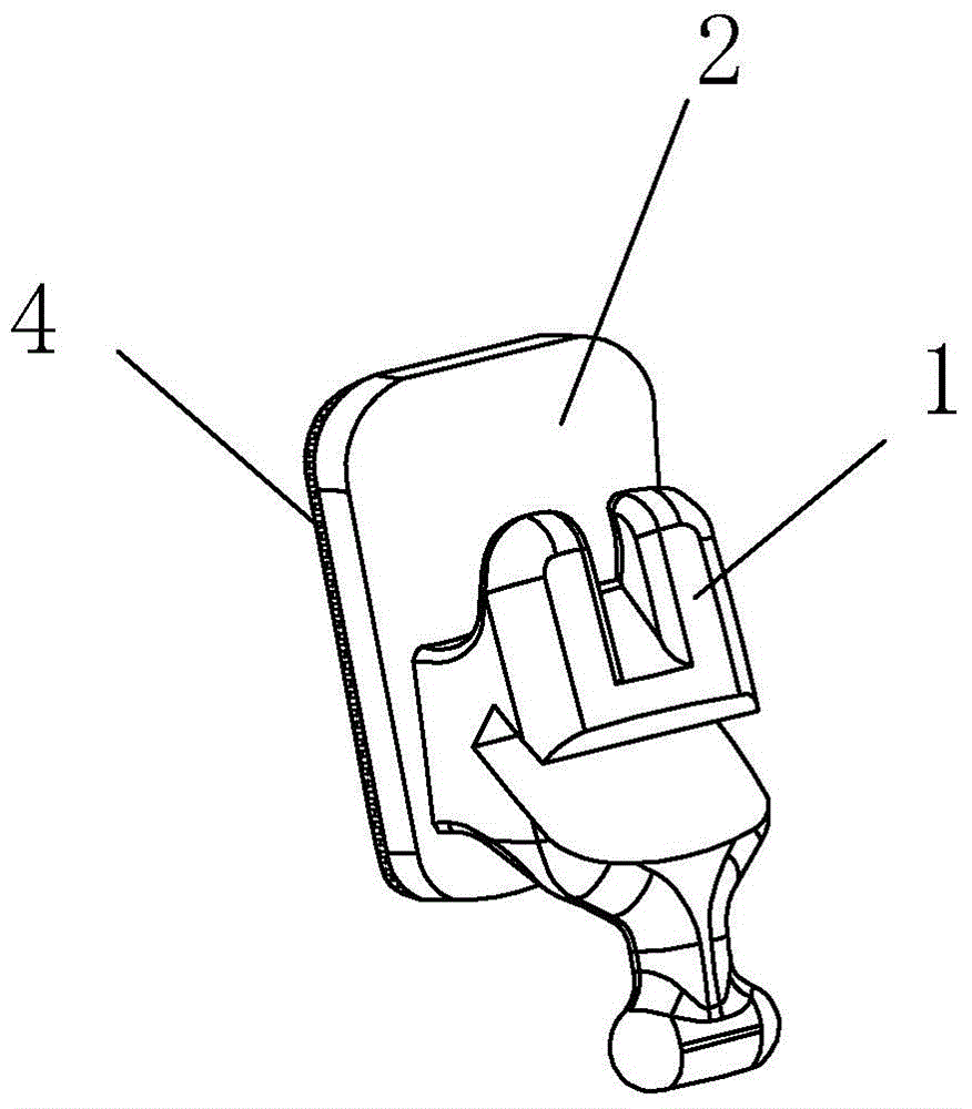
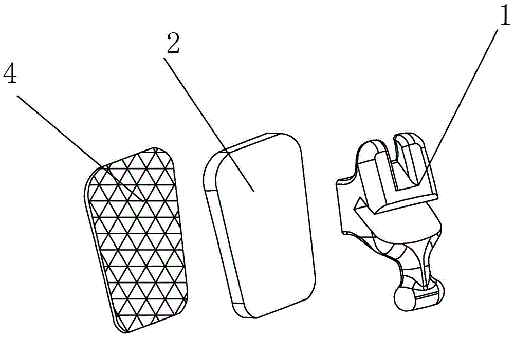
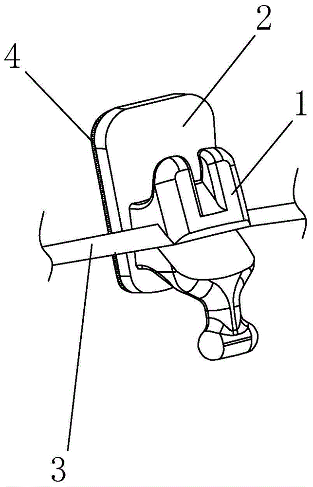
[0027] Attached below Figure 1-6 The represented embodiment further describes the present invention:

[0028] Steps include:

[0029] a) Three-dimensional scanning of the patient's teeth by laser to obtain three-dimensional imaging information including the patient's teeth, dentition, alveolar bone and cranio-maxillofacial bone structure;

[0030] b) Combining the obtained 3D imaging information, use computer-aided design and manufacturing technology (CAD / CAM technology) to simulate and correct the teeth on the computer, and determine the tooth model plan after obtaining the ideal dentition effect and matching the arch diagram of the dentition ;

[0031] c) Use a 3D printer to print out the simulated orthodontic tooth model plan;

[0032] d) Use computer-aided design and manufacturing technology (CAD / CAM technology) based on the center point of the dentition on the printed tooth model, the space between the teeth, the slope of the tooth surface, the surface shape of the ar...


PUM


Abstract

Disclosed is a manufacturing method of a customized tongue-side invisible aligner, and belongs to the technical field of orthodontic treatment. The manufacturing method comprises steps of: performing three-dimensional scanning of a patient's teeth via laser to obtain image information; performing simulative alignment of teeth on a computer to obtain an ideal tooth alignment effect, and determining a tooth model scheme; printing the tooth model scheme of simulative alignment by using a 3D printer; designing three-dimensional models of an aligning bracket, a bracket baseplate, and an aligning steel wire, which are special for each tooth, by computer aided design and manufacturing technology. The manufacturing method is characterized by further comprising: carving the aligning bracket by adopting stainless steel via a numerically-controlled machine tool; selecting a stainless steel board, and carving a shape, identical to the teeth, at the lower surface of the stainless steel board via the numerically-controlled machine tool; and selecting a stainless steel mesh and welding the stainless steel mesh to the lower surface of the stainless steel board. According to the manufacturing method, an integrate bracket is manufactured by directly adopting three-dimensional image information, so that the bracket is high in precision and good in comfort during an orthodontic treatment process.

Description

technical field [0001] The invention belongs to the technical field of orthodontics, and in particular relates to a manufacturing method of a personalized lingual invisible aligner. Background technique [0002] Orthodontics (orthodontics) has experienced more than a century of development since Dr. Angle founded the world's first orthodontic specialist school as a branch of stomatology in 1901. In the first 30 years, the development of orthodontic appliances received the most attention. The invention of the North American square wire arch appliance and the European functional orthodontic appliance are undoubtedly breakthroughs. The former controls the movement of teeth in three dimensions and provides a guarantee for the establishment of a good relationship; the latter It is used for early treatment to regulate the growth of the jaw. In the following 30 years, the diagnosis and correction design of dislocation deformity became a research hotspot, and the advent of X-ray ce...

Claims


Application Information

Patent Timeline
IPC IPC(8): A61C7/14
Inventor 徐小寒
Owner JINHUA KEDIFU MEDICAL TECH CO LTD
Why Eureka
Try Eureka