Photocatalyst reactor, photocatalyst reaction tower and flue gas purification system

A photocatalyst and reactor technology, which is applied in the field of flue gas purification system and photocatalyst reactor, can solve the problems of high-sulfur coal consumption restrictions, high operating costs, pungent smell, etc., to increase the probability of contact and contact time, Improve the efficiency of catalytic reaction and the effect of uniform distribution of fluid resistance

Active Publication Date: 2015-10-21
WISDRI ENG & RES INC LTD
View PDF5 Cites 4 Cited by
  • Summary
  • Abstract
  • Description
  • Claims
  • Application Information

AI Technical Summary

Problems solved by technology

Second, there are certain restrictions on the use of high-sulfur coal
Because NH has not reacted in the above temperature range 3 will react with SO in combustion products 3 The reaction produces ammonium bisulfate [NH 4 HSO 4 ], will stick to the air preheater or other downstream components, causing blockage and corrosion, affecting the normal operation of the unit
Finally, the escape of ammonia due to incomplete reaction with NOx will occur, which not only produces a pungent smell and white ammonium chloride fume, but also ammonia is adsorbed on the fly ash, making the disposal and utilization of the dust difficult
[0008] 2) The existing technology cannot achieve simultaneous desulfurization and denitrification, and it is necessary to install a set of devices for each
Therefore, the investment is large and the operating cost is high

Method used


Image

  • Photocatalyst reactor, photocatalyst reaction tower and flue gas purification system
  • Photocatalyst reactor, photocatalyst reaction tower and flue gas purification system
  • Photocatalyst reactor, photocatalyst reaction tower and flue gas purification system

Examples


Embodiment Construction

[0032] The following will clearly and completely describe the technical solutions in the embodiments of the present invention with reference to the accompanying drawings in the embodiments of the present invention. Obviously, the described embodiments are only some, not all, embodiments of the present invention. Based on the embodiments of the present invention, all other embodiments obtained by persons of ordinary skill in the art without making creative efforts belong to the protection scope of the present invention.

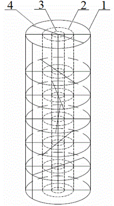
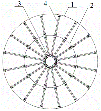
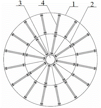
[0033] Such as figure 1 , The embodiment of the present invention provides a photocatalyst reactor for simultaneous desulfurization and denitrification of flue gas. The reactor includes a support column 3, an annular partition 2 and a shell 1 coaxially arranged in sequence from the inside to the outside, and the annular partition 2 divides the space between the support column 3 and the shell 1. Separated into an inner ring space and an outer ring space; one e...


PUM


Abstract

The invention relates to a photocatalyst reactor. The photocatalyst reactor comprises a support pillar, an annular partition board and a shell which are coaxially arranged in sequence from inside to outside, and the space between the support pillar and the shell are divided into an inner ring space and an outer ring space by the annular partition board; a first flue gas inlet is formed in one end of the shell, and a first flue gas outlet is formed in the other end of the shell; the inner ring space and the outer ring space are each internally provided with multiple reaction layers in the flue gas circulation direction, each reaction layer is composed of multiple photocatalyst reaction units which are arranged in an annular pattern, and each photocatalyst reaction unit is arranged to be perpendicular to the flue gas circulation direction. In addition, a photocatalyst reaction tower and a flue gas purification system are further provided. By means of each of the photocatalyst reactor, the photocatalyst reaction tower and the flue gas purification system, the desulfuration and denitration can be achieved simultaneously, the photocatalysis efficiency and reaction homogenization degree are high, and a good desulfuration and denitration effect is achieved.

Description

technical field [0001] The invention relates to a photocatalyst reactor, a photocatalyst reaction tower and a flue gas purification system, belonging to the technical field of environmental protection. Background technique [0002] my country is the world's largest coal producer and consumer, as well as the world's largest steel producer. About 84% of my country's coal is directly burned. In 2014, China's crude steel output accounted for 49.5% of the world's total crude steel output, reaching 822.7 million tons. A large amount of coal burning and iron and steel smelting have caused serious air pollution in our country. There are many kinds of pollutants discharged into the atmosphere, including smoke, sulfur oxides, nitrogen oxides, organic compounds, halides, carbon compounds, etc.; some of them are smoke and some are gases. Environmental pollution such as acid rain, greenhouse effect and ozone layer depletion caused by these pollutants has seriously affected the living e...

Claims


Application Information

Patent Timeline
Patent Type & Authority Applications(China)
IPC IPC(8): B01D53/90B01D53/60
Inventor 薛军锋阮祥志陈世意段炼
Owner WISDRI ENG & RES INC LTD
Why Eureka
Try Eureka