
Technology and system for combined use of calcium carbide furnace and vertical furnace

A calcium carbide furnace and calcium carbide technology, applied in the field of metallurgy, can solve the problems of high power consumption, high cost, increased production cost, etc., and achieve the effects of large flue gas production, uniform heat distribution, and saving system investment.

Active Publication Date: 2015-11-11
SHENWU TECH GRP CO LTD
View PDF4 Cites 2 Cited by
  • Summary
  • Abstract
  • Description
  • Claims
  • Application Information

AI Technical Summary

Problems solved by technology

[0002] Calcium carbide is the main raw material for the production of ethylene, and occupies a very important position in the industry. The production of calcium carbide is to mix a certain proportion of quicklime and semi-coke (coke) to send the charge into the electric furnace through the feeding device and the feeding pipe. The main structure of the electric furnace includes Furnace body and electrodes, when the calcium carbide furnace works, it relies on the electric arc generated after energization, and relies on the high temperature formed by the arc to heat the charge to make the charge reach the heat required for chemical reaction. Among them, the area where the high temperature emitted by the arc can directly act is called the arc work area or melting The position of this area is from the bottom of the electrode end to the bottom of the furnace. The structure of the traditional calcium carbide furnace is a circular three-phase electrode structure. The three electrodes are arranged inside the furnace body in an equilateral triangle, and the outer furnace body is circular. Disadvantages of the calcium carbide furnace structure: there are many places around the furnace where the arc cannot function or the effect is very poor, that is, the non-melting pool area, so that the temperature in these places cannot meet the reaction requirements, and the charge in this area cannot or is difficult to react. Due to the large difference in heat distribution, the productivity of the calcium carbide furnace is low, the power consumption is high, the consumption of semi-coke (coke) is relatively large, and the cost is high
[0003] Shaft furnaces are widely used in the field of oxidative roasting of iron ore pellets or direct reduction of iron. In the iron and steel metallurgy industry, they are used for oxidative roasting of iron ore pellets or direct reduction of pellets to iron. They are indispensable process equipment in iron and steel metallurgy. The shaft furnace directly requires a lot of heat and consumes a lot of reducing gas during the smelting process, which increases production costs

Method used


Image

  • Technology and system for combined use of calcium carbide furnace and vertical furnace
  • Technology and system for combined use of calcium carbide furnace and vertical furnace
  • Technology and system for combined use of calcium carbide furnace and vertical furnace

Examples


Embodiment 1

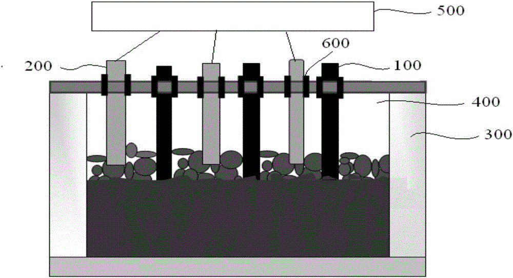
[0055]A calcium carbide furnace with a spray gun includes a furnace cover, a spray gun body, a spray gun lifting device, and an insulating sealing sleeve. The calcium carbide furnace is a calcium carbide furnace with a spray gun installed on the furnace cover, and the spray gun is a copper spray gun. In this embodiment, the spray gun structure is as figure 2 As shown, the spray gun is equipped with oxygen injection pipe, coal powder injection pipe and cooling water pipe. The oxygen injection pipe / coal powder injection pipe is connected with the external oxygen pipe / high-pressure coal powder delivery pipe. When the furnace is sprayed with oxygen and coal, open the control valve to control the pressure and flow. The cooling water pipe of the spray gun is connected with the high-pressure net ring water pipe, so that the cooling water circulates rapidly in the spray gun to ensure that the inlet water temperature is less than 35°C and the outlet water temperature is less than 50°...

Embodiment 2

[0058] A calcium carbide furnace with a spray gun includes a furnace cover, a spray gun body, a spray gun lifting device, and an insulating sealing sleeve. The calcium carbide furnace is a calcium carbide furnace with a spray gun installed on the furnace cover, and the spray gun is a copper spray gun. In this embodiment, the spray gun structure is as figure 2 As shown, the spray gun is equipped with oxygen injection pipe, coal powder injection pipe and cooling water pipe. The oxygen injection pipe / coal powder injection pipe is connected with the external oxygen pipe / high-pressure coal powder delivery pipe. When the furnace is sprayed with oxygen and coal, open the control valve to control the pressure and flow. The cooling water pipe of the spray gun is connected with the high-pressure net ring water pipe, so that the cooling water circulates rapidly in the spray gun to ensure that the inlet water temperature is less than 35°C and the outlet water temperature is less than 50...


PUM

PropertyMeasurementUnit
particle diameteraaaaaaaaaa

Abstract

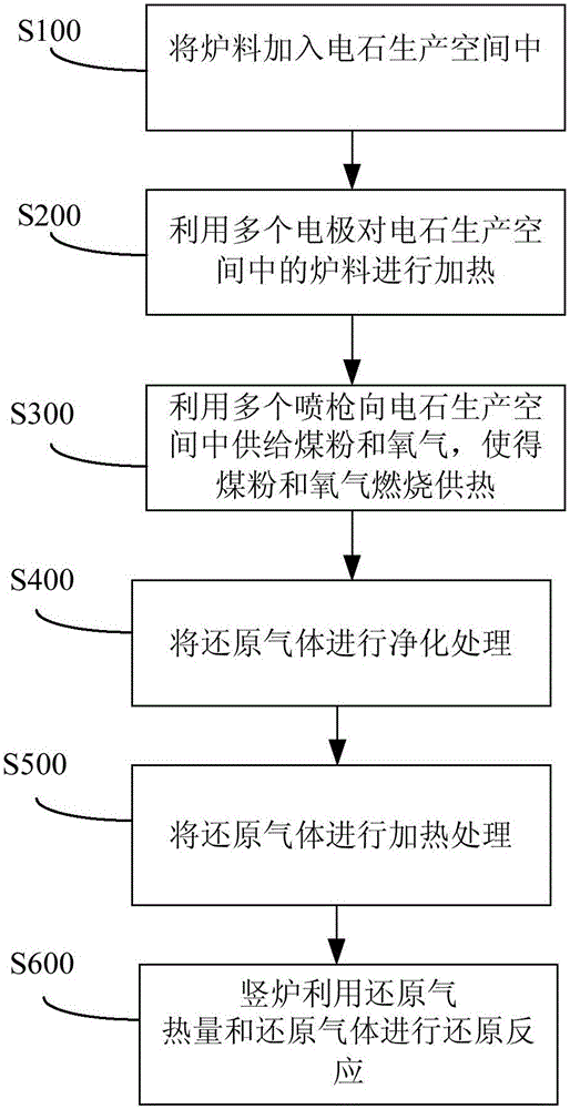
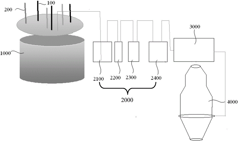
The invention discloses a technology and system for combined use of a calcium carbide furnace and a vertical furnace. The system for combined use of the calcium carbide furnace and the vertical furnace comprises the calcium carbide furnace used for preparing calcium carbide and obtaining reducing gas, a purifying device connected with the calcium carbide furnace and used for purifying the reducing gas for conveniently obtaining the clean reducing gas, a heating furnace connected with the purifying device and used for heating the clean reducing gas for conveniently obtaining the high-temperature reducing gas, and the vertical furnace connected with the heating furnace and used for conducting a reducing reaction through the high-temperature reducing gas. Smoke which is high in reducing gas content and generated in the process of preparing the calcium carbide through the calcium carbide furnace can provide heat and a reducing agent for the vertical furnace after being purified and heated, waste is utilized, system investment for preparing the reducing gas is reduced, and the production cost of vertical furnace products is reduced.

Description

technical field [0001] The invention relates to the field of metallurgy, in particular to a combined process and system for a calcium carbide furnace and a shaft furnace. Background technique [0002] Calcium carbide is the main raw material for the production of ethylene and occupies a very important position in the industry. The production of calcium carbide is to mix a certain proportion of quicklime and semi-coke (coke) to send the charge into the electric furnace through the feeding device and the feeding pipe. The main structure of the electric furnace includes Furnace body and electrodes, when the calcium carbide furnace works, it relies on the electric arc generated after energization, and relies on the high temperature formed by the arc to heat the charge to make the charge reach the heat required for chemical reaction. Among them, the area where the high temperature emitted by the arc can directly act is called the arc work area or melting The position of this area...

Claims


Application Information

Patent Timeline
Patent Type & Authority Applications(China)
IPC IPC(8): C01B31/32C21B13/02C22B1/214C01B32/942
Inventor 邓君薛逊曹志成张岚范志辉孟嘉乐唐敬坤吴道洪
Owner SHENWU TECH GRP CO LTD
Learn More