
A kind of dsoi strain gauge and manufacturing method thereof

A manufacturing method and technology of strain gauges, applied in the direction of electric/magnetic solid deformation measurement, electromagnetic measurement devices, etc., can solve the problems of large output temperature drift, large offset voltage of full-bridge circuit, and reduced yield, so as to improve measurement accuracy , Reduce the offset voltage, reduce the effect of electric leakage

Active Publication Date: 2019-05-10
广东和宇传感器有限公司 +2
View PDF5 Cites 1 Cited by
  • Summary
  • Abstract
  • Description
  • Claims
  • Application Information

AI Technical Summary

Problems solved by technology

[0005] Existing monocrystalline silicon strain gauges generally adopt an epitaxial structure, and the bridge resistors are isolated by a P-N junction. There is a reverse leakage current of the P-N junction, which causes a large output temperature drift and cannot work in a high temperature environment.
At the same time, when the existing monocrystalline silicon strain gauge is transplanted to the glass glue on the elastic film for micro-melting, the relative position between the bridge resistances is easy to change, because the size of the bridge resistance is extremely small (width and thickness) Both are on the order of microns), as long as the relative position between the resistance strips changes slightly, it will cause a small change in the bridge resistance, and this change will cause the offset voltage of the full bridge circuit to increase, reducing the yield

Method used


Image

  • A kind of dsoi strain gauge and manufacturing method thereof
  • A kind of dsoi strain gauge and manufacturing method thereof
  • A kind of dsoi strain gauge and manufacturing method thereof

Examples


Embodiment Construction

[0046] The present invention will be described in further detail below in conjunction with the accompanying drawings and embodiments.

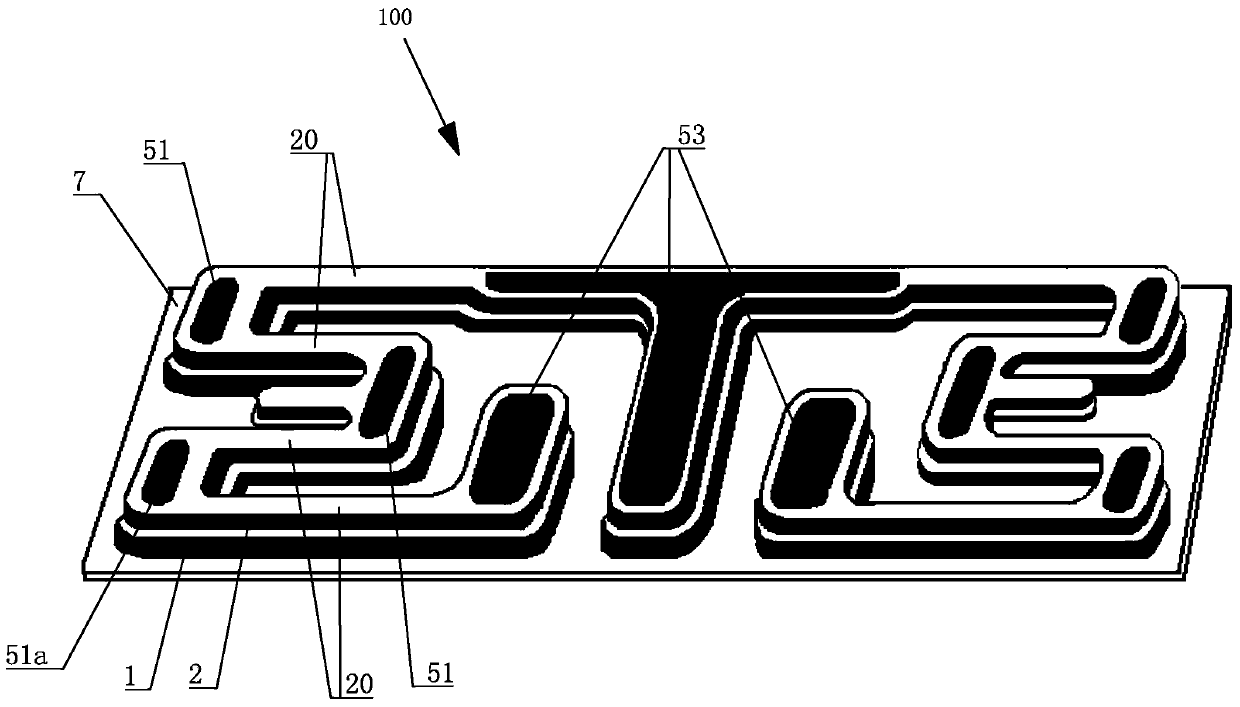
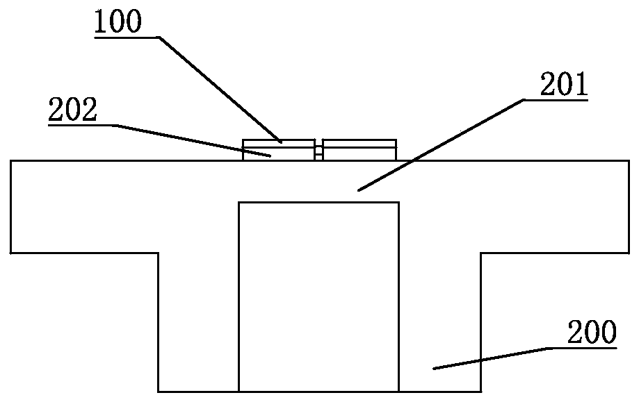
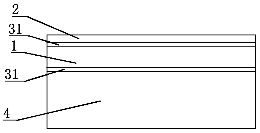
[0047] refer to Figure 1 to Figure 16, a DSOI (double silicon oxide insulation) strain gauge of the present invention, including a strain gauge 100, the entire structure of the strain gauge 100 is divided into two layers, including a device film layer 2 with an upper surface of 2-5µm and a lower surface of 12-15µm The substrate layer 1 is used to support the upper surface layer. The device thin film layer 2 can be made of single crystal silicon or polycrystalline silicon material. The substrate layer 1 can be made of single crystal silicon or polycrystalline silicon material. The thick insulating film layer 31 is isolated, instead of the P-N junction isolation, to ensure the absolute isolation of electrical properties between the two, and to improve the working temperature range of the sensor, which can meet the requirements of the sensor in ...


PUM


Abstract

The invention discloses a DSOI (Double Silicon Oxide Insulation) strain gage and a manufacturing method thereof. The gage comprises a substrate layer and a thin-film layer for components. The thin-film layer for components is arranged on the substrate layer; the thin-film layer for components and the substrate layer are separated by an insulation thin film layer. The thin-film layer for components comprises at least one resistor sensitive grating; each resistor sensitive grating is provided with at least two resistor bars that are in series connection; the bottom of the substrate layer is provided with an insulation film base which is in connection with the resistor sensitive grating(s). Such a structure reduces power leakage and enables a transducer to work at a wider temperature range; at the same time, as the insulation film base at the bottom of the substrate layer connects the gage as a whole, the positions of the resistor bars inside the resistor sensitive grating(s) are relatively stable, and consequently the misappropriate voltage across a whole circuit is reduced and the substrate layer and an elastic film are prevented from direct exposure to harmful materials contained in glass glue. In this manner, the insulation function and voltage withstanding function between a gage and an elastic film are improved.

Description

technical field [0001] The invention relates to the field of pressure sensors, in particular to a DSOI strain gauge and a manufacturing method thereof. Background technique [0002] In the field of high-pressure sensors ranging from 6Mpa to 200Mpa, the packaging structure has become a prominent contradiction, and the O-ring seal can no longer resist the pressure leakage problem under high temperature and high pressure conditions. Therefore, in the high-voltage sensor, the pressure-sensitive bridge resistance is generally made on the 17-4PH stainless steel base, and then the base is welded to the interface end of the stainless steel shell by argon arc welding, electron beam, high-energy laser beam, etc. Ensure that the back of the base can withstand thousands of kilograms of pressure without air leakage. [0003] At present, the large-range pressure sensors or transmitters at home and abroad mainly have the following two structures: (1) One is a fully enclosed sputtering fil...

Claims


Application Information

Patent Timeline
IPC IPC(8): G01B7/16
Inventor 沈绍群罗小勇梁栋汉
Owner 广东和宇传感器有限公司
Learn More