
A voltage doubler soft switching push-pull DC converter

A technology of DC converter and soft switch, which is applied in the direction of converting DC power input to DC power output, instruments, and adjusting electric variables, etc. It can solve the problems of reducing the volume and weight of the transformer, large on-state loss, and reducing conversion efficiency. Achieve the effects of reducing device stress and switching noise, solving voltage spike problems, and improving efficiency

Active Publication Date: 2018-05-08
NANJING UNIV OF AERONAUTICS & ASTRONAUTICS
View PDF4 Cites 0 Cited by
  • Summary
  • Abstract
  • Description
  • Claims
  • Application Information

AI Technical Summary

Problems solved by technology

However, the traditional push-pull DC converter works in a hard switching state. As the switching frequency increases, the switching loss is large and the conversion efficiency is low. In addition, the reverse recovery characteristics of the rectifier diode on the secondary side of the transformer cause a large High voltage spikes bring serious interference; in practical applications, it is often necessary to add active and passive clamping snubber circuits, which bring additional losses and further reduce conversion efficiency
For this reason, Chinese invention patent publication number is that CN103078514A discloses a kind of push-pull converter with voltage doubling resonance capability, and it comprises primary side push-pull circuit, high-frequency transformer, secondary side voltage doubling circuit and secondary side resonant circuit; The gain of the converter is improved by using the voltage doubler structure, and the turn ratio of the transformer is reduced by half under the condition of obtaining the same voltage gain, which reduces the volume and weight of the transformer; the resonant circuit on the secondary side of the transformer allows the diode to be turned off with zero current, which solves the problem However, the power tube of the push-pull circuit on the primary side of the transformer is still working in a hard switching state, and a voltage spike will be generated when the power tube is turned off, which increases the voltage stress of the device
In addition, the Chinese Invention Patent Publication No. CN102111075A has invented a voltage doubler rectification push-pull forward converter. Replacement to achieve voltage doubling effect, which effectively reduces the turn ratio of the transformer, realizes the zero current turn-off of the diode, and suppresses the voltage peak on the primary power tube of the transformer, but the primary power tube is still working under hard switching conditions , the switching loss is larger
Chinese Journal of Electrical Engineering, Volume 32, Issue 33, Pages 23 to 30 in 2012 proposed a ZVS (zero voltage) three-tube push-pull DC converter, which is connected in series between the input voltage source and the intermediate winding of the transformer. An auxiliary tube is used to realize the zero-voltage turn-on of the power tube. However, the converter circulates approximately 1 / 2 of the maximum input current, and the on-state loss is large. It is difficult for the auxiliary tube to achieve soft switching under light load.

Method used


Image

  • A voltage doubler soft switching push-pull DC converter
  • A voltage doubler soft switching push-pull DC converter
  • A voltage doubler soft switching push-pull DC converter

Examples


Embodiment Construction

[0022] In order to describe the present invention more specifically, the technical solutions of the present invention will be described in detail below in conjunction with the accompanying drawings and embodiments.

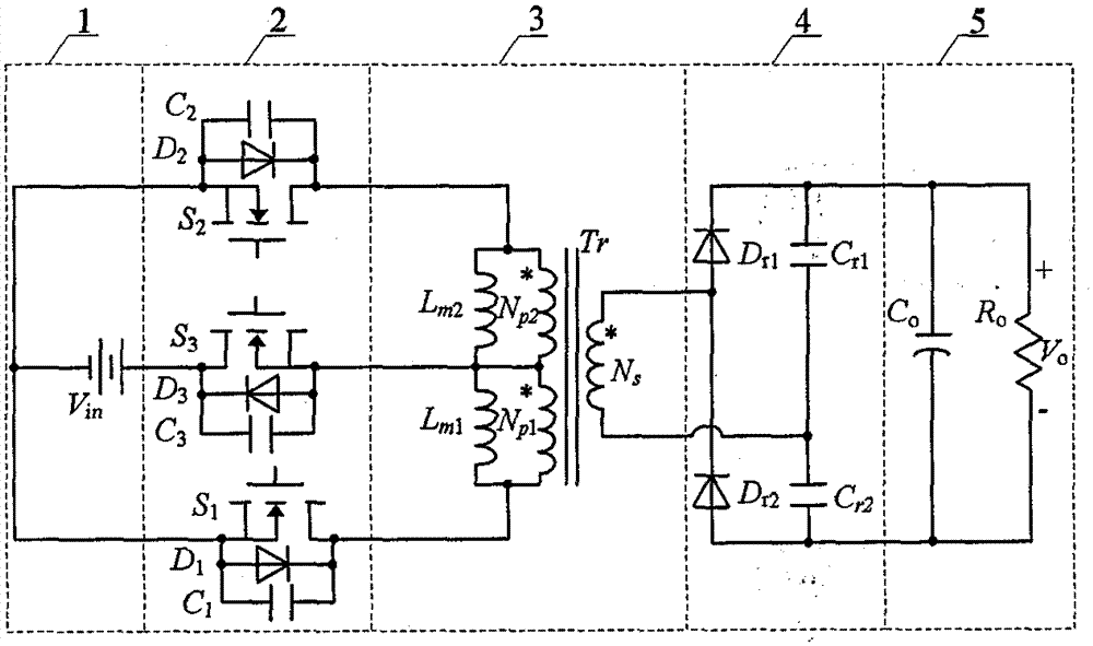
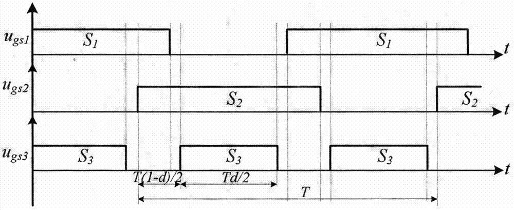
[0023] attached figure 1 , attached figure 2 A schematic structural diagram of a voltage-clamping soft-switching push-pull DC converter proposed by the present invention and a corresponding PWM switch timing diagram.

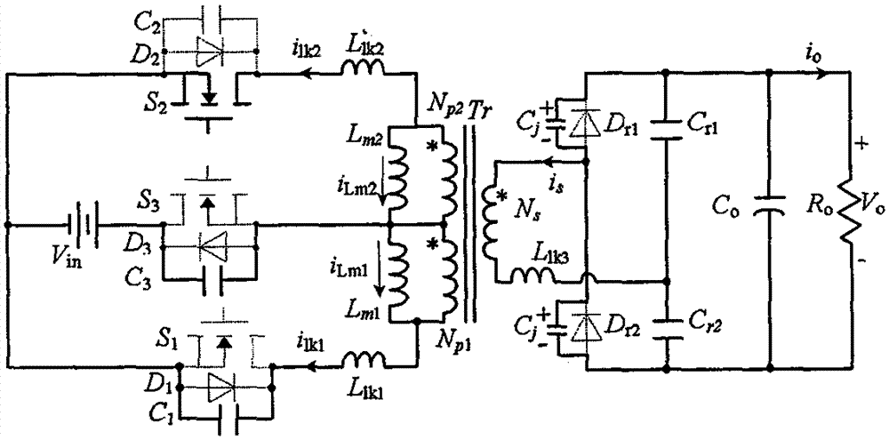
[0024] attached image 3 It is a schematic structural diagram of the implementation circuit of the voltage doubler soft switching push-pull DC converter of the present invention. It consists of a DC voltage source, three power tubes, a high-frequency isolation transformer, a voltage doubler rectifier circuit, a filter capacitor and a load. S 1 ~S 3 are three power tubes, D 1 ~D 3 Respectively power tube S 1 ~S 3 body diode, C 1 ~C 3 S respectively 1 ~S 3 The parasitic capacitance, TX is the isolation transformer, L lk1 , L lk2 , L l...


PUM


Abstract

The invention discloses a voltage-doubling type soft switching push-pull DC converter, which structurally comprises a DC voltage source Vin(1), first, second and third power transistors S1, S2, S3 (2) with anti-parallel diodes and junction capacitors, a high-frequency isolation transformer Tr(3), a voltage-doubling rectifying circuit (4), a capacitor filtering circuit and an output load (5), wherein the high-frequency isolation transformer Tr (3) comprises a primary-side first winding NP1, a primary-side second winding NP2 and a secondary-side winding Ns. According to the invention, a filter inductor is removed from the converter, thereby being conducive to reducing the size and the weight of the converter; a voltage-doubling rectification structure is adopted to improve step-up ratio of the converter, the turn ratio of the high-frequency isolation transformer is reduced under the same input / output voltage level, and the size and the weight of the transformer are reduced; the power transistors of the converter can realize zero-voltage turn-on and turn-off, thereby reducing the switching loss; and the rectifier diode is zero-current turn-off, thereby solving problems of voltage stress and loss brought about by reverse recovery of the diode, and improving the work efficiency of the converter.

Description

technical field [0001] The invention relates to the technical field of DC-DC soft-switching converters, in particular to a voltage doubler type soft-switching push-pull DC converter and a power electronic converter. Background technique [0002] In new energy power generation such as solar energy, wind energy, and biomass energy, fuel cell power generation, and energy storage systems, because the voltage of the system energy storage device is very low, it is usually necessary to boost the lower voltage to a higher voltage through a DC / DC converter. The DC voltage can meet the requirements of the subsequent inverter for the DC bus voltage. This requires the DC / DC converter to have the characteristics of high gain and high conversion efficiency. In these applications, the push-pull DC converter is favored due to its relatively simple structure, electrical isolation, and the ability to adjust the transformer turns ratio to match the input and output voltage levels. However, t...

Claims


Application Information

Patent Timeline
Patent Type & Authority Patents(China)
IPC IPC(8): H02M3/337
CPCY02B70/10
Inventor 伍群芳王勤徐佳林陈仲肖岚
Owner NANJING UNIV OF AERONAUTICS & ASTRONAUTICS
Learn More