A waste liquid zero discharge treatment device and its treatment method

A treatment device and zero-emission technology, applied in the direction of gaseous effluent wastewater treatment, combined devices, separation methods, etc., can solve the problems of increased energy consumption, aggravated ash deposition and scaling, etc., to reduce losses, enhance high-intensity sound wave energy, The effect of improving the utilization rate

Active Publication Date: 2018-02-02
NANJING CHANGRONG ACOUSTIC INC
View PDF6 Cites 0 Cited by
  • Summary
  • Abstract
  • Description
  • Claims
  • Application Information

AI Technical Summary

Problems solved by technology

[0005] The purpose of the present invention is to provide a brand-new waste liquid zero discharge treatment device and its treatment method in order to overcome the above deficiencies in the prior art. The device uses a high-energy sounding device and a unique static pressure expansion design to form solid-liquid-gas separation The device solves the zero-discharge treatment method of solid-liquid separation through high-temperature evaporation. The pipeline in front of the dust removal device is caused by the continuous passage of salt after crystallization in the waste water. The problem of aggravated ash accumulation and scaling in parts can effectively avoid related problems such as increased energy consumption of boiler units, passive shutdown of boiler units, excessive discharge of air pollutants such as smoke and dust due to ash accumulation and fouling blockage, and comprehensively realize energy saving and environmental protection and zero discharge of waste water and waste gas Target

Method used


Image

  • A waste liquid zero discharge treatment device and its treatment method
  • A waste liquid zero discharge treatment device and its treatment method

Examples


Embodiment 1

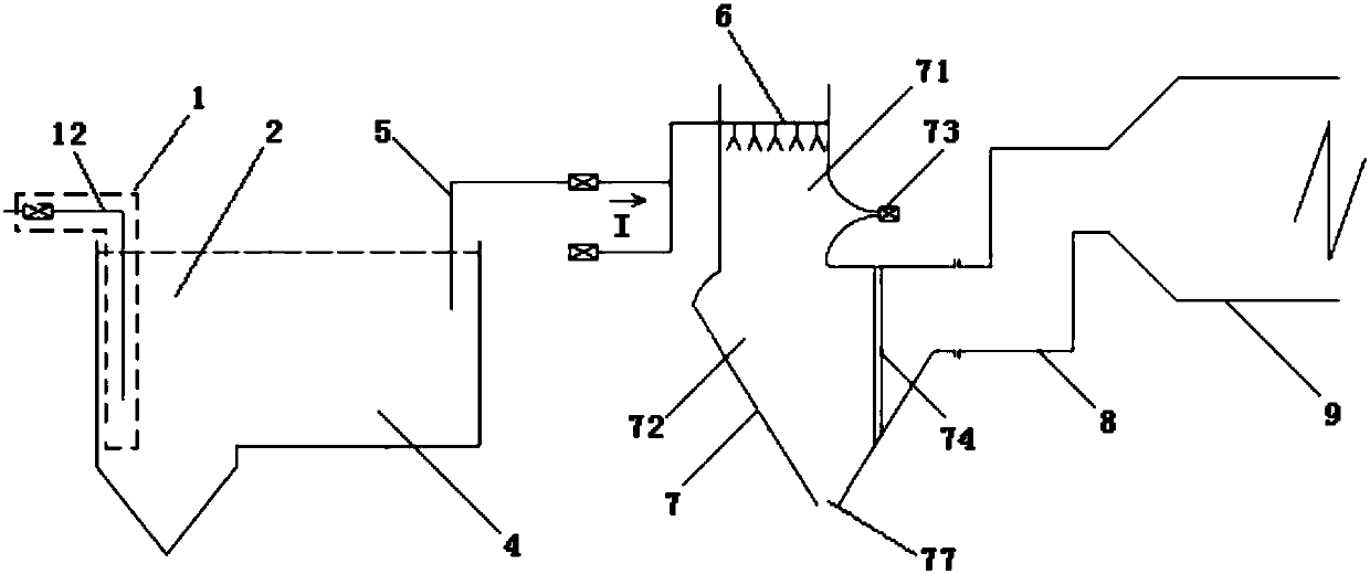
[0049] Such as figure 1 As shown, it is a schematic diagram of the waste liquid zero discharge treatment device provided in the embodiment. It can be seen that the whole device includes waste liquid conveying equipment 1, pre-sedimentation tank 2, buffer tank 4, atomization equipment 6, and solid-liquid-gas separation device 7 And the dedusting device 9, wherein the water delivery pipe 12 of the waste liquid delivery equipment 1 extends into the pre-sedimentation tank 2, the pre-settling tank 2 communicates with the buffer tank 4, and the buffer tank 4 is connected with the atomization device 6 through the water delivery pipe 5; The atomization equipment includes a high-pressure pump 61, an air compressor 62, an atomization pipeline, and an atomization nozzle; the solid-liquid-gas separation device 7 includes a top inlet, and an atomization zone 71 is arranged below the top inlet, and a static pressure zone 71 is arranged below the atomization zone 71. The expansion area 72, t...

Embodiment 2

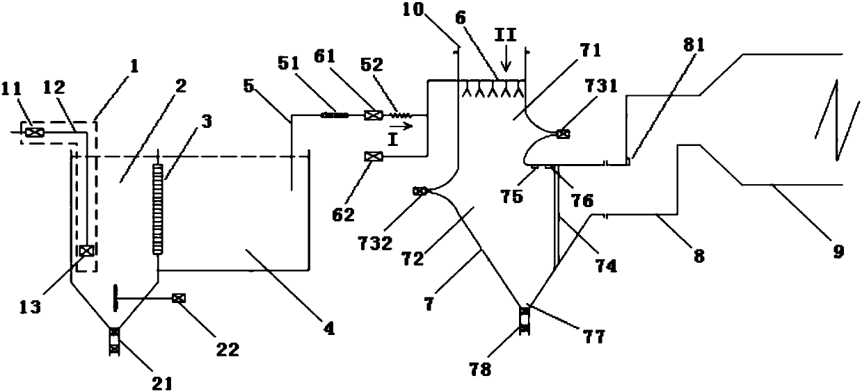
[0052] Such as figure 2 As shown, it is a schematic diagram of the waste liquid zero discharge treatment device provided in this embodiment. It can be seen that it has been further improved on the basis of Embodiment 1, wherein the waste liquid conveying equipment 1 includes a slurry pump 11 and a water delivery pipe 12 And the decompression flow equalization device 13, the decompression flow equalization device 13 is arranged at the water delivery outlet of the water delivery pipe 12, the decompression flow equalization device 13 gradually expands the capacity of the end of the water delivery pipe 12 to form a pressure buffer zone, and is set in the pressure buffer zone One or more layers of orifice plates with uniform perforation rate reduce the pressure and decelerate the liquid flowing out of the water delivery pipe 12 and flow through the orifice plates. The waste water enters the pre-sedimentation tank 2 after decompression and uniform flow, which is more conducive to t...

Embodiment 3

[0055] Taking the desulfurization wastewater of a 1000MW unit of a power plant using the waste liquid zero discharge treatment device provided by the present invention as an example, the specific treatment method of the waste liquid zero discharge treatment device provided by the present invention will be described. Specifically include the following steps:

[0056](1) The desulfurization waste water after the desulfurization of the desulfurization tower is sent to the pre-sedimentation tank 2 by the slurry pump 11 through the water delivery pipe 12 through the decompression and flow equalization device 13, and then reaches the pre-sedimentation tank 2, and is stirred at a constant speed by the agitator 22 in the pre-settling tank 2 This makes the precipitation distribution more uniform, and the supernatant after preliminary precipitation separation is filtered by the first filter 3 and then reaches the buffer pool 4 .

[0057] (2) After the waste water in the buffer pool 4 is...


PUM


Abstract

The invention discloses a waste liquid zero discharge processing device and a processing method thereof. The processing device includes waste liquid conveying equipment, a pre-sedimentation tank, a buffer tank, atomization equipment, a solid-liquid-gas separation device and a dust removal device, and waste liquid conveying equipment. The water pipe is connected to the pre-sedimentation tank, the pre-sedimentation tank is connected to the buffer tank, and the buffer tank is connected to the atomization equipment through the water supply pipe; the atomization equipment is installed at the entrance of the top of the solid-liquid-gas separation device, and the gas outlet of the solid-liquid-gas separation device is connected to the dust collector through the pipeline. The device is connected. The treatment method is that the waste water enters the buffer tank through the pre-sedimentation tank, and then enters the top entrance of the solid-liquid-gas separation device after being atomized by the atomization equipment; the high-temperature air flow is passed through the top entrance to evaporate the water in the atomized small droplets to obtain The impurity particles are condensed by the high-intensity sound waves emitted by the sound-generating device to form larger agglomerated parcels, enter a stall state through the static pressure expansion area, accelerate to sink and be discharged. The invention further purifies the waste water through the unique design of the device, and finally achieves the goal of zero discharge.

Description

technical field [0001] The invention relates to a waste liquid treatment device and a treatment method thereof, in particular to a waste liquid zero discharge treatment device used in thermal power, steel and other fields. Background technique [0002] With the progress of society and the development of economy, the pollution of thermal power plants to the atmospheric environment has been widely concerned by people. Therefore, it is a severe challenge for the sustainable development of my country's energy field to effectively reduce pollutant emissions and improve the impact on the environment. [0003] At present, the existing flue gas desulfurization technologies include wet desulfurization and dry desulfurization. Among them, wet desulfurization technology is the most widely used. Wet flue gas desulfurization is a technological process adopted by about 85% of large thermal power plants in the world today. Due to the high content of mercury, lead, nickel, arsenic and chr...

Claims


Application Information

Patent Timeline
Patent Type & Authority Patents(China)
IPC IPC(8): C02F9/10B01D51/08B01D50/00C02F103/18
Inventor 张荣初邹怡然闻小明孙卫国杨文文杨于生
Owner NANJING CHANGRONG ACOUSTIC INC
Why Eureka
Try Eureka