Coke oven flue-gas waste-heat and dry-quenching waste-heat coupled power generation system and coupled power generation method thereof

A technology of flue gas waste heat and power generation system, which is applied to furnaces, furnace components, waste heat treatment and other directions, can solve the problems of large loss of CDQ waste heat power generation technology, imperfect manufacturing technology, low thermal efficiency of waste heat boilers, etc. The effect of value utilization, reducing floor space and reducing waste

Inactive Publication Date: 2016-01-27
NORTH CHINA UNIVERSITY OF SCIENCE AND TECHNOLOGY
View PDF5 Cites 10 Cited by
  • Summary
  • Abstract
  • Description
  • Claims
  • Application Information

AI Technical Summary

Problems solved by technology

[0006] The manufacturing technology is not yet perfect, and the thermoelectric conversion efficiency is only about 8%.
[0007] (2) Relatively high investment
figure 1 It is a schematic diagram of a CDQ power generation system in a coking plant. It can be seen from the figure that the exhaust gas temperature of CDQ is 178.5°C, and the thermal efficiency of the waste heat boiler is also low. Due to the expansion of high-temperature gas, the power consumption of the circulating fan is also low. higher
At the same time, it can also be seen from the figure that the heat transfer temperature difference between the cold and heat sources of each heating surface is relatively large, so the loss of CDQ waste heat power generation technology is relatively large

Method used


Image

  • Coke oven flue-gas waste-heat and dry-quenching waste-heat coupled power generation system and coupled power generation method thereof

Examples


Embodiment Construction

[0036] In order to facilitate the understanding of those skilled in the art, the present invention will be further described in detail below in conjunction with the drawings and specific embodiments.

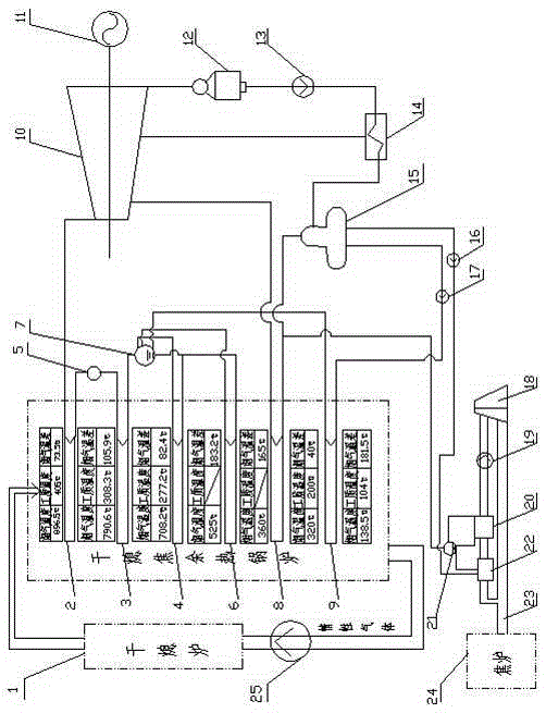
[0037] see figure 1 , a coke oven flue gas waste heat and CDQ waste heat coupled power generation system, including CDQ waste heat recovery device, coke oven flue gas waste heat recovery device, turbogenerator set and condensing device; wherein CDQ waste heat recovery device

[0038] It includes a CDQ furnace 1 and a CDQ waste heat boiler connected to each other; inside the CDQ waste heat boiler includes a CDQ secondary superheater 2, a CDQ primary superheater 3, a first evaporator 4, and a second CDQ superheater arranged in sequence. Evaporator 6, coke oven flue gas waste heat superheater 8 and CDQ economizer 9, CDQ waste heat boiler is also equipped with CDQ drum 7, CDQ drum 7 is connected to CDQ primary superheating at the same time device 3, the first evaporator 4, the seco...


PUM


Abstract

The invention relates to a coke oven flue-gas waste-heat and dry-quenching waste-heat coupled power generation system and a coupled power generation method thereof. The system comprises a dry-quenching waste-heat recycling device and the dry-quenching waste-heat recycling device comprises a dry-quenching furnace and a dry-quenching waste-heat boiler which are communicated with each other. A dry-quenching secondary superheater, a dry-quenching primary superheater, a first evaporator, a second evaporator, a coke oven flue-gas waste-heat superheater and a dry-quenching economizer are sequentially arranged in the dry-quenching waste-heat boiler. A coke oven flue-gas waste-heat recycling device comprises a coke oven. A coke oven flue-gas main channel is connected to the coke oven and sequentially connected with a coke oven flue-gas waste-heat economizer, a coke oven flue-gas waste-heat evaporator, a coke oven flue-gas draught fan and a coke oven flue-gas chimney. A steam turbine generator unit, the dry-quenching waste-heat recycling device and the coke oven flue-gas waste-heat recycling device form a loop through a condensing unit. According to the coke oven flue-gas waste-heat and dry-quenching waste-heat coupled power generation system and the coupled power generation method, coupled power generation is achieved in the manner that coking flue exhaust fume waste heat enters dry-quenching waste-heat power generation circulation in a coupled manner, and the purposes of efficient utilization of secondary energy and energy saving and emission reduction are achieved.

Description

technical field [0001] The invention relates to a coke oven flue gas waste heat and CDQ waste heat coupled power generation system and a coupled power generation method thereof, belonging to the field of waste heat power generation. Background technique [0002] With the rapid development of the national economy, the production capacity of my country's coking industry has also experienced rapid growth. According to relevant data, in 2012, there were 299 large-scale coke ovens with a capacity of more than 500,000 tons in my country, and the total coke production capacity reached 408.21 million tons. In the coking equipment and technology commonly used in my country, the temperature of the waste gas produced by the coke oven is generally between 220°C and 260°C, and the sensible heat contained in the waste gas of the coke oven produced per ton of coke is 19426KJ / ton (coke). The recoverable sensible heat contained in coke oven exhaust gas in the industry is as high as 7.93×10 1...

Claims


Application Information

Patent Timeline
Patent Type & Authority Applications(China)
IPC IPC(8): F01K11/02F27D17/00
CPCY02P10/25
Inventor 张玉柱王子兵胡长庆邢红伟王乙竹于勇王新东杨潇潇赵申王超常建黄博秦万扩辛世界齐立军
Owner NORTH CHINA UNIVERSITY OF SCIENCE AND TECHNOLOGY
Why Eureka
Try Eureka