
Device and method for recycling petroleum and phenol from oilfield industry wastewater and treating and regenerating wastewater

A technology for oil production wastewater and wastewater treatment, which is applied in the fields of resource recycling and environmental engineering, and can solve problems such as failure to meet the discharge standard of COD less than or equal to 50mg/L, consumption of large flocculants and coagulants, and difficulty in recovering oil and processing , to achieve the effect of reducing sludge treatment costs, saving chemical costs, and containing less impurities

Inactive Publication Date: 2016-03-16
罗依依
View PDF6 Cites 23 Cited by
  • Summary
  • Abstract
  • Description
  • Claims
  • Application Information

AI Technical Summary

Problems solved by technology

To sum up, although there are many oil production wastewater treatment technologies, none of the discharged water after treatment by the existing oil production wastewater treatment technology can meet the emission standard of COD less than or equal to 50 mg / L, and has the following disadvantages:
[0012] 1. The water quality indicators of oil production wastewater after oil recovery usually cannot meet the discharge standards required in the "Technical Specifications for Oil Production Wastewater Treatment Engineering" (HJ2041-2014);
[0013] 2. The recovered oil contains a large amount of impurities, which makes it difficult to process the recovered oil for subsequent use;
[0014] 3. The oil production wastewater is directly air flotation after gravity settlement, which consumes a lot of flocculants and coagulants, resulting in high operating costs;
[0015] 4. A large amount of oily sludge will be produced, and the further treatment of sludge will generate more costs

Method used


Image

  • Device and method for recycling petroleum and phenol from oilfield industry wastewater and treating and regenerating wastewater
  • Device and method for recycling petroleum and phenol from oilfield industry wastewater and treating and regenerating wastewater
  • Device and method for recycling petroleum and phenol from oilfield industry wastewater and treating and regenerating wastewater

Examples


Embodiment 1

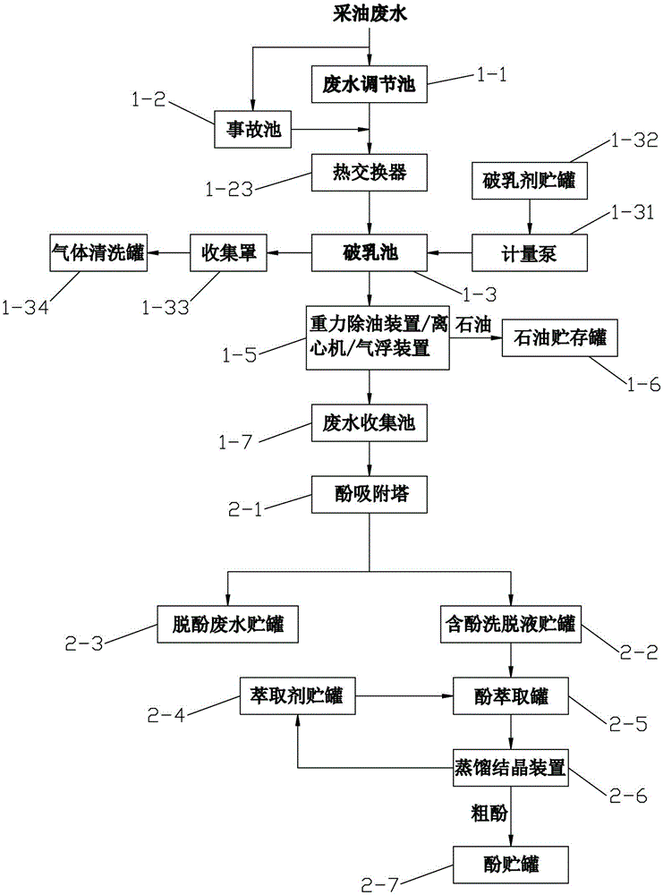
[0076] (1) Demulsification: Collect the oil production wastewater into the wastewater regulating tank 1-1 through the pipeline and mix it evenly in the wastewater regulating tank 1-1, adjust the water volume of the wastewater, and detect that its oil content is 50mg / L, COD is 300mg / L, The SS is 50mg / L, the salt content is 1000mg / L, and the pH is 6.5. Pump the oil production wastewater that has passed through the wastewater adjustment tank into the demulsification tank 1-3, add sulfuric acid to adjust the pH to 6 for demulsification, and press 5g / m 3 Join PAM.

[0077] (2) Oil recovery: pump the oil production waste water obtained from the demulsification in step (1) into the gravity deoiling device 1-5, and separate and recover the oil by gravity sedimentation to obtain 49g / m 3 And deoiled oil production wastewater, petroleum is stored in petroleum storage tanks 1-6, deoiled oil production wastewater is stored in wastewater collection pools 1-7, and the COD of wastewater drop...

Embodiment 2

[0090] (1) Demulsification: Collect the oil production waste water in the regulating pool 1-1 through the pipeline and mix it evenly in the regulating pool 1-1, adjust the water volume of the waste water, and detect that the oil content is 6000mg / L, the COD is 7000mg / L, and the SS is 500mg / L, salt content 20000mg / L, pH 9.5. Pump the oil production wastewater that has passed through the adjustment tank into the pH adjustment tank (demulsification tank) 1-3, add sulfuric acid to adjust the pH to 2 to break the emulsion, and press 10g / m 3 Join PAM.

[0091] (2) Oil recovery: the oil production wastewater obtained in step (1) demulsification is separated and recovered by a centrifuge to obtain 5998g / m of oil 3 And deoiling wastewater, oil is stored in storage tanks 1-6, deoiling wastewater is stored in wastewater collection pools 1-7, and the COD of wastewater drops from 7000mg / L to 892mg / L.

[0092] The centrifugal separation is to pump the demulsified oil production wastewater...

Embodiment 3

[0105] (1) Demulsification: Collect the oil production wastewater into the wastewater regulating tank 1-1 through the pipeline and mix it evenly in the wastewater regulating tank 1-1, adjust the water volume of the wastewater, and detect that its oil content is 450mg / L, COD is 610mg / L, The SS is 200mg / L, the salt content is 3200mg / L, and the pH is 7.2. Pump the oil production wastewater that has passed through the wastewater adjustment tank into the demulsification tank 1-3, add sulfuric acid to adjust the pH to 4 for demulsification, and press 4g / m 3 Join PAM.

[0106] (2) Oil recovery: pump the oil extraction waste water obtained from step (1) demulsification into the centrifuge 1-5 for separation, and recover 448g / m of oil 3 and oil production wastewater after deoiling, petroleum is stored in oil storage tanks 1-6, and oil production wastewater after deoiling is stored in wastewater collection pools 1-7.

[0107] The centrifugal separation is to pump the demulsified oil r...


PUM

PropertyMeasurementUnit
Grainaaaaaaaaaa

Abstract

The invention discloses a device for recycling petroleum and phenol from oilfield industry wastewater and treating and regenerating wastewater. The device disclosed by the invention comprises a petroleum recycling unit, a phenol recycling unit, a biochemical treatment unit, an electrolysis unit, a deep wastewater treatment unit, a desalted regenerated water production unit and a sludge treatment unit. A method of the device disclosed by the invention sequentially comprises the following steps: demulsifying, recycling petroleum, recycling phenol, carrying out anaerobic treatment, carrying out aerobic treatment, carrying out electrolysis treatment, carrying out membrane treatment or biochemical treatment by virtue of a biological aerated filter, and desalting. The device and method which are disclosed by the invention have the advantages that petroleum and phenol in the oilfield industry wastewater are recycled, a wax component is recycled, and wastewater is effectively treated, so that resource recycling is realized while oilfield industry wastewater pollution is treated, and wastewater quality can meet emission standards in technical specification for oilfield industry wastewater treatment (HJ2041-2014).

Description

technical field [0001] The present invention relates to recovery of oil phenol in oil extraction wastewater and a device and method for wastewater treatment and regeneration, in particular to a combined treatment of pH adjustment, gravity sedimentation separation, centrifugal separation or air flotation, adsorption, anaerobic, aerobic and other processes from oil extraction wastewater The invention discloses a device and method for recovering petroleum and phenol and waste water treatment and regeneration, belonging to the fields of resource recovery and utilization and environmental engineering. Background technique [0002] At present, my country's onshore oil fields basically adopt the water injection development method, that is, inject high-pressure water into the formation to drive crude oil to be extracted from the oil well. After a period of water injection, the injected water will be produced together with the crude oil. As the development time prolongs, the water co...

Claims


Application Information

Patent Timeline
IPC IPC(8): C02F9/14C02F11/00C02F11/12C02F103/10
CPCC02F1/04C02F1/24C02F1/26C02F1/38C02F1/40C02F1/441C02F1/442C02F1/444C02F1/46104C02F1/467C02F1/4691C02F1/4693C02F3/00C02F3/02C02F3/28C02F9/00C02F11/00C02F11/121C02F2001/5218C02F2103/10
Inventor 罗依依
Owner 罗依依
Learn More