
Wet flue gas desulfurization tower with deep dehumidification function and dehumidification process

A wet flue gas desulfurization and desulfurization tower technology, applied in the field of wet flue gas desulfurization, can solve the problems of reducing chimney anti-corrosion investment, complex system, high cost, etc. The effect of heat increase

Active Publication Date: 2016-03-23
SHANDONG UNIV
View PDF4 Cites 9 Cited by
  • Summary
  • Abstract
  • Description
  • Claims
  • Application Information

AI Technical Summary

Problems solved by technology

After the flue gas is washed and desulfurized by the desulfurization spray layer, and most of the droplets are removed by the demister, the saturated wet flue gas with a temperature of about 50 ° C and a relative humidity of 100% is discharged through the wet chimney. Due to the temperature difference between the wet flue gas and the atmosphere, The water vapor in the saturated wet flue gas will condense rapidly at the chimney outlet when it is cold, forming the phenomenon of "white smoke" and "chimney rain", and forming acid liquid inside the chimney to corrode the structure of the chimney, and the low temperature of the flue gas directly leads to the deterioration of the chimney Weak ability to lift and spread air
[0004] In order to solve the problems of "white smoke" and "chimney rain", coal-fired power plants have used rotary heat exchangers (RGGH) or tubular heat exchangers (MGGH) to heat the flue gas downstream of the wet desulfurization tower to reduce the humidity of the wet flue gas. Years of operation results show that the heat exchanger is easy to block, has high resistance, high failure rate, and complex system, and has been gradually eliminated and dismantled by power plants; in order to ensure the safe operation of chimneys, coal-fired power plants use titanium plates, glass fiber reinforced plastics, etc. Chimney linings to protect the chimney structure from corrosion, costly
[0005] At present, there is still no technology in engineering application that can avoid the discharge of saturated wet flue gas from the desulfurization tower, so as to simplify the downstream equipment of the desulfurization tower, reduce the anti-corrosion investment of the chimney, and avoid the phenomenon of "white smoke" and "chimney rain"

Method used


Image

  • Wet flue gas desulfurization tower with deep dehumidification function and dehumidification process
  • Wet flue gas desulfurization tower with deep dehumidification function and dehumidification process

Examples


Embodiment 1

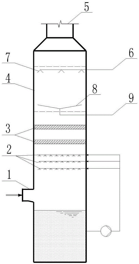
[0031] A wet flue gas desulfurization tower with deep dehumidification function. The inlet of the desulfurization tower is connected to the inlet flue 1, and the top is the flue gas outlet 5. The desulfurization tower is equipped with a desulfurization spray layer 2 and a demister in sequence from the middle to the upper part. 3 and a dehumidifier 4, the dehumidifier 4 includes a dehumidification nozzle 7 and a liquid contact device 8 located below the dehumidification nozzle 7, the top of the dehumidifier is provided with a dehumidification working fluid inlet 6, the dehumidification working fluid inlet 6 is connected to the dehumidification nozzle 7, and the liquid contact device The middle part of 8 connects dilute working medium outlet 9.

[0032] The coal-fired flue gas enters the desulfurization tower through the inlet flue 1, and after being washed and desulfurized by the desulfurization spray layer 2, and most of the liquid droplets are removed by the demister 3, the sa...

Embodiment 2

[0037] The difference between this embodiment and embodiment 1 is:

[0038] Fillers are arranged below the dehumidification nozzle 7 to increase the mass transfer area, reduce the equipment volume and improve the dehumidification efficiency.

Embodiment 3

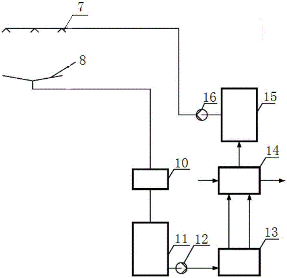
[0040] Such as figure 2 As shown, the liquid contact device 8 is connected to the working medium pool 15, and a purifier 10, a dilute working medium pool 11 and a water-liquid separator 13 are arranged successively between the liquid contact device 8 and the working medium pool, and the water-liquid separator 13 The vapor pressure of the dilute working fluid in the (flash evaporator) is higher than the water vapor partial pressure of the air in the water-liquid separator 13; Input to the dehumidifier 4, spray and absorb water vapor through the dehumidification nozzle 7 to form a dilute working fluid, then the dilute working fluid flows into the dilute working fluid pool 11 after being purified by the purifier, and is input to the water-liquid separator 11 through the dilute working fluid pump 12 Realize the separation of dehumidification working fluid and water, and the separated dehumidification working fluid is sent to the working fluid pool after cooling for recycling agai...


PUM


Abstract

The invention discloses a wet flue gas desulfurization tower with a deep dehumidification function and a dehumidification process. Desulfurization spraying layers, demisters and a dehumidifier are sequentially arranged in the desulfurization tower from the middle part to the upper part, wherein the dehumidifier comprises dehumidification nozzles and a liquid receiving device arranged below the dehumidification nozzles. The wet flue gas desulfurization tower has the benefits as follows: the wet flue gas desulfurization tower integrates functions of desulfurization, demisting and dehumidification, and flue gas discharged from the desulfurization tower is not saturated wet flue gas with 100% relative humidity, but unsaturated and wet flue gas with adjustable and controllable relative humidity; the dew point temperature of the flue gas is reduced, the temperature is increased, the superheat degree is improved, the phenomena of white smoke and stack rain formed due to flue gas condensation are fundamentally avoided, and expensive materials used for corrosion prevention of a chimney are not required; the system flow is simplified, the equipment function integration degree is high, and the device occupies little land.

Description

technical field [0001] The invention relates to the technical field of wet flue gas desulfurization, in particular to a wet flue gas desulfurization tower which integrates the functions of desulfurization, demisting and deep dehumidification, can reduce the humidity of exhaust gas, and eliminate "white smoke" and "chimney rain". dehumidification process. Background technique [0002] Most coal-fired power plants in my country use wet flue gas desulfurization processes, including limestone-gypsum method, ammonia method, and seawater desulfurization. They use limestone slurry, ammonia water, or seawater to spray and wash the flue gas in the desulfurization tower. During this process, the SO in the flue gas 2 Absorbed by the absorption liquid to achieve the removal of SO 2 the goal of. [0003] The desulfurization tower is the core device of the wet desulfurization process. Generally, the empty tower spraying process is adopted. The desulfurization tower is composed of three ...

Claims


Application Information

Patent Timeline
IPC IPC(8): B01D53/78B01D47/06B01D53/14B01D53/18B01D47/14F23J15/04F23J15/06
CPCB01D47/06B01D47/14B01D53/1425B01D53/1493B01D53/18B01D53/78B01D2247/04B01D2252/10F23J15/003F23J15/04F23J15/06
Inventor 董勇吕扬崔琳
Owner SHANDONG UNIV
Learn More