A graphite deposition device for a chemical vapor deposition furnace

A chemical vapor deposition and deposition device technology, applied in the field of graphite deposition devices for chemical vapor deposition furnaces, can solve problems such as inconvenient operation, uneven product thickness, and reduced product utilization

Active Publication Date: 2019-06-25
安徽光智科技有限公司
View PDF6 Cites 0 Cited by
  • Summary
  • Abstract
  • Description
  • Claims
  • Application Information

AI Technical Summary

Problems solved by technology

In general chemical vapor deposition systems, the graphite deposition devices used are basically single chambers, that is, only one deposition chamber is set up in the entire deposition system. This single chamber graphite deposition component is more suitable for small furnaces. Convenient, but for furnaces used in large-scale industrial production, in the process of chemical vapor deposition, defects of uneven thickness of products produced in the entire deposition chamber usually appear, which reduces the utilization rate of products and increases the back-end processing difficulty
Moreover, the graphite deposition device using a single chamber not only has relatively high production costs, but also is inconvenient to operate, resulting in low production efficiency
[0006] Therefore, how to obtain a graphite deposition device for a chemical vapor deposition furnace, which can overcome the defect of uneven product thickness in the deposition chamber in large-scale industrial production, has always been one of the focuses of common attention of manufacturers and users in the industry.

Method used


Image

  • A graphite deposition device for a chemical vapor deposition furnace
  • A graphite deposition device for a chemical vapor deposition furnace
  • A graphite deposition device for a chemical vapor deposition furnace

Examples


Embodiment 1

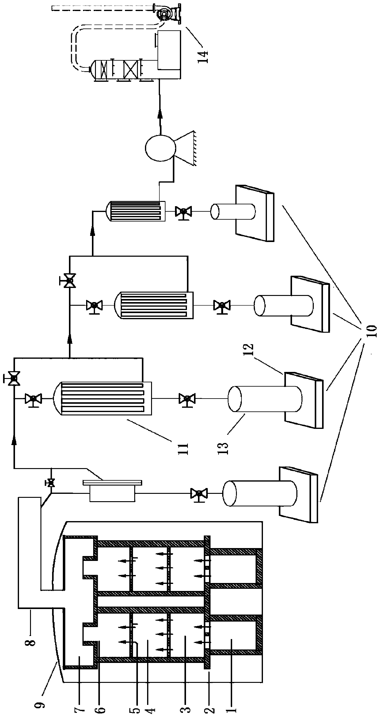
[0063] First, put the solid raw material into the graphite crucible of the solid raw material holding device, cover the crucible lid on the top, and confirm that the airflow holes on the top of the crucible lid are in good condition.

[0064] Then set the temperature rise and deposition procedures of the chemical vapor deposition furnace. During the deposition process, the solid raw material vapor and gas raw materials are carried by inert gas and enter the first deposition chamber through the pores. After the deposition part of the bottom cover of the first deposition chamber, Then enter the second deposition chamber through the airflow holes on the partition (arranged alternately with the airflow holes on the cover). After the bottom partition of the second deposition chamber is deposited, it finally passes through the airflow holes on the partition (the first The bottom partition of the second deposition chamber and the airflow holes on the bottom partition of the third deposit...

Embodiment 2

[0067] Load the zinc raw material into the graphite crucible, set the temperature rise and deposition program, during the deposition process, hydrogen selenide and zinc vapor enter the deposition chamber under the inert gas, first enter the first deposition chamber, and deposit part in the first deposition chamber , And then enter the second deposition chamber through the gas splitter plate for deposition. After the deposition part of the bottom partition of the second deposition chamber, enter the third deposition chamber through the gas flow holes on the partition, and deposit in the third deposition chamber. On the bottom partition of the third deposition chamber. Finally, the unreacted gas and undeposited zinc selenide dust enter the dust collection chamber for deposition, and then pass through the dust guide channel to enter the back-end dust multi-stage collection system and tail gas treatment system after the chemical deposition process.

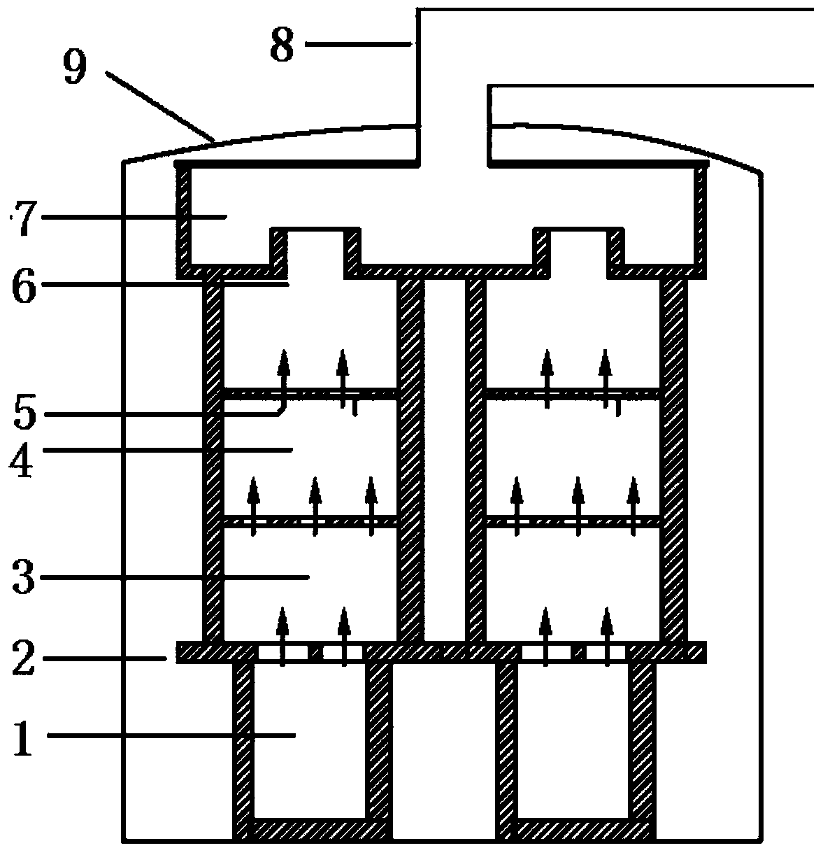
[0068] See figure 2 , figure 2 ...

Embodiment 3

[0072] Load the zinc raw material into the graphite crucible, set the temperature rise and deposition program, during the deposition process hydrogen sulfide and zinc vapor enter the deposition chamber under the inert gas, first enter the first deposition chamber, in the first deposition chamber, the deposition part, Then enter the second deposition chamber through the gas splitter plate for deposition, and finally the unreacted gas and undeposited zinc sulfide dust enter the dust collection chamber for deposition, and then enter the back end dust collection system after the chemical deposition process through the dust guide channel And exhaust gas treatment system.

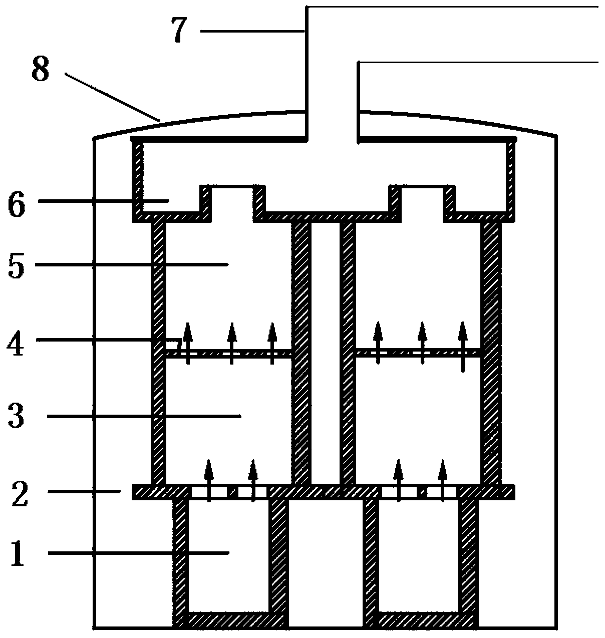
[0073] See image 3 , image 3 This is a schematic diagram of the structure of a graphite deposition apparatus for a chemical vapor deposition furnace provided in Example 3 of the present invention, where 1 is a crucible, 2 is a crucible cover, 3 is a first deposition chamber, 4 is a partition, and 5 is a second I...


PUM


Abstract

The invention provides a graphite deposition device for a chemical vapor deposition furnace, comprising: a solid raw material storage device; a cover plate placed on the top of the solid raw material storage device; an airflow hole is arranged on the cover plate; at least two The deposition mechanism of more than two vertically arranged deposition chambers; the deposition mechanism is arranged on the top of the cover plate, and the cover plate is used as the bottom plate of the deposition mechanism; a partition is arranged between the deposition chambers, and a partition is arranged on the partition There are airflow holes; a dust collection chamber located above the deposition chamber; the bottom of the dust collection chamber communicates with the uppermost deposition chamber through a dust collection channel. The present invention adds partitions in the deposition chamber, divides the entire chamber, makes the thickness of the products deposited in different chambers more uniform, presents a gradient, improves the conversion rate of the product, greatly improves the subsequent processing efficiency, and reduces the Difficulty in processing, improve the overall utilization rate of products, and effectively solve the problem of uneven thickness in the deposition process of large-scale deposition chambers.

Description

Technical field [0001] The invention relates to the technical field of chemical vapor deposition, in particular to a graphite deposition device for a chemical vapor deposition furnace. Background technique [0002] Modern science and technology require the use of a large number of new inorganic materials with different functions. These functional materials must be highly pure, or doped materials formed by deliberately mixing high purity materials with certain impurities. Chemical vapor deposition is a new technology for preparing inorganic materials developed in recent decades. Chemical vapor deposition has been widely used to purify substances, develop new crystals, and deposit various single crystal, polycrystalline or glassy inorganic thin film materials. [0003] Chemical vapor deposition is a vapor growth method for preparing materials. It is to pass one or several compounds and elemental gases containing film elements into the reaction chamber where the substrate is placed, ...

Claims


Application Information

Patent Timeline
Patent Type & Authority Patents(China)
IPC IPC(8): C23C16/44C23C16/30
CPCC23C16/306C23C16/44
Inventor 朱刘于金凤刘留
Owner 安徽光智科技有限公司
Why Eureka
Try Eureka