
Vertical-type tubular furnace infrared carbon sulfur analyzer

An infrared carbon and sulfur analysis, tube furnace technology, which is applied in the analysis of materials, chemical analysis by combustion, and material analysis by optical means, etc., can solve the problems of broken combustion tubes, shortened service life of combustion tubes, and limited use space. , to achieve the effect of accurate pick and place position, long service life and sufficient combustion

Active Publication Date: 2016-04-13
NCS TESTING TECH
View PDF4 Cites 13 Cited by
  • Summary
  • Abstract
  • Description
  • Claims
  • Application Information

AI Technical Summary

Problems solved by technology

Horizontally installed combustion tubes and heating elements are easily deformed and broken under the influence of high temperature and gravity; when the cold porcelain boat is pushed into the high-temperature combustion tube, it will also cause the combustion tube to break due to excessive temperature difference, thus greatly shortening the combustion tube. and the service life of silicon carbide rods
In addition, in the traditional method, porcelain boats are used to hold the samples, the space is limited, the samples are easy to be scattered, and the products after the burning of the samples are easy to splash or be missed in the combustion tube, thus shortening the service life of the combustion tube
[0004] Traditional positioning devices only use a single positioning method of photoelectric sensors
Due to the position error of the conveyor belt during the transmission process, the positioning is inaccurate;
[0005] The traditional gas circuit design adopts one-way oxygen gas supply and the horizontal structure of the furnace. The combustion process of the sample is not sufficient and takes a long time, usually 3 to 5 minutes.

Method used


Image

  • Vertical-type tubular furnace infrared carbon sulfur analyzer
  • Vertical-type tubular furnace infrared carbon sulfur analyzer

Examples


Embodiment Construction

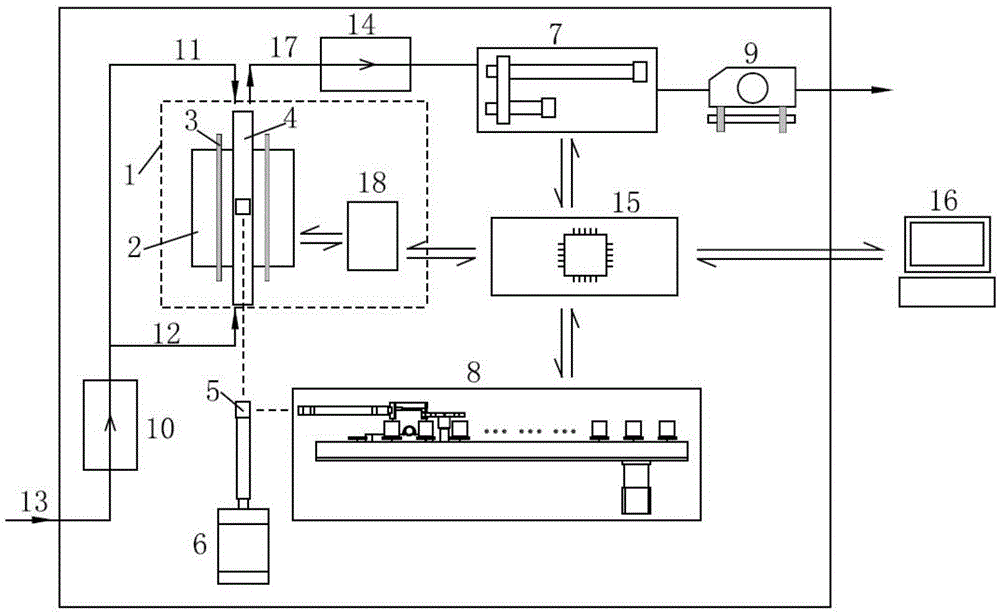
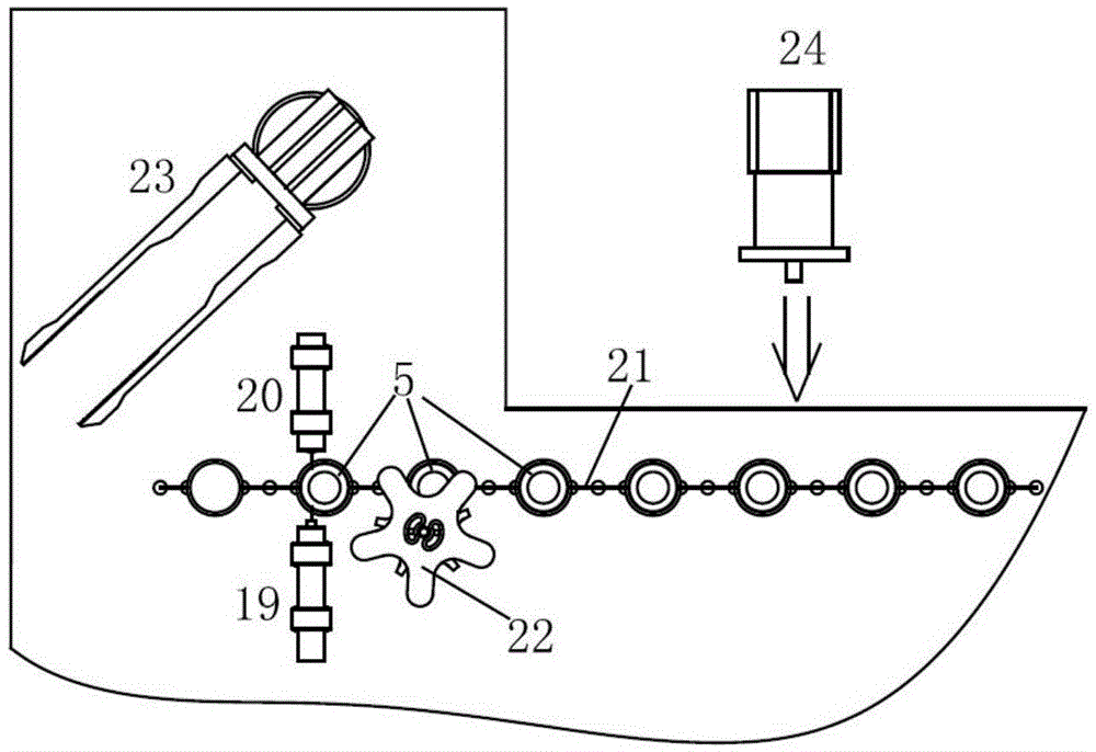
[0034] figure 1 , figure 2 It is a specific embodiment of the present invention.

[0035] The invention consists of a tubular furnace heating system 1, a fully automatic sample adding system, a gas circuit system with a vacuum pump, an infrared detection system 7, and a data acquisition and control system. The automatic sampling system is installed under the heating system 1 of the tube furnace, and pushes the crucible containing the sample into the combustion tube; Between the furnace heating system 1 and the vacuum pump, the carbon dioxide and sulfur dioxide in the combusted analysis gas are detected; the data acquisition and control system are respectively connected to the temperature control device 18, the infrared detection system 7, and the automatic sampling device through the data connection line 8 connections to control and collect signals.

[0036] Among them, the tube furnace heating system 1 is composed of a furnace 2, a silicon carbide rod 3, a combustion tube...


PUM


Abstract

A vertical-type tubular furnace infrared carbon sulfur analyzer belongs to the technical field of gas elemental analysis in a material, comprises a tubular furnace heating system (1), a fully-automatic sampling system, a gas path system with a vacuum pump, an infrared detection system, a signal acquisition system and a signal processing system, the fully-automatic sampling system is installed below the tubular furnace heating system (1), and is used for pushing a crucible, in which a sample is contained, into a combustion tube; the vacuum pump is installed at the terminal end of a gas path to achieve gas flow stability in the whole gas path system; the infrared detection system (7) is mounted between the tubular furnace heating system (1) and the vacuum pump and is used for detection of carbon dioxide and sulfur dioxide in an analysis gas after combustion; a data acquisition and control system is connected via a data connection line, respectively with a temperature control device (18), the infrared detection system (7) and a fully-automatic sampling device (8), and is used for signal control and acquisition. Advantages are that the analysis is fast and results are stable.

Description

technical field [0001] The invention belongs to the technical field of gas element analysis in materials, and in particular provides a vertical tube furnace infrared carbon and sulfur analyzer; Rapid analysis of carbon and sulfur in non-ferrous metals such as nickel, rare earth metals such as praseodymium, neodymium and dysprosium, solid and liquid inorganic and organic materials such as cement, ceramics, ore, coal, coke, slag, catalyst, crude oil and rubber. Background technique [0002] The invention relates to a tube furnace heating system, a fully automatic sample adding system, a gas path system with a vacuum pump and an infrared detection system, which is especially suitable for the analysis of carbon and sulfur components in materials. [0003] In the traditional tube furnace carbon and sulfur analyzer, the heating furnace, combustion tube and silicon carbide rods are all installed horizontally. The sample is placed in a porcelain boat, manually pushed into the combus...

Claims


Application Information

Patent Timeline
IPC IPC(8): G01N35/10G01N31/12G01N21/3504
CPCG01N21/3504G01N31/12G01N35/10
Inventor 黄小峰吴利民张长均王学华何小意王蓬杨植岗
Owner NCS TESTING TECH
Learn More