Design and manufacturing method of porous grid structure material

A grid structure, porous material technology, used in additive processing, medical science, prosthesis, etc., can solve the problems of uncertainty, blindness of porous material performance, etc., to improve mechanical and physical properties, shorten structural design and Product manufacturing time, the effect of broadening the range of material processing

Inactive Publication Date: 2016-04-20
BEIJING UNIV OF TECH
View PDF6 Cites 25 Cited by
  • Summary
  • Abstract
  • Description
  • Claims
  • Application Information

AI Technical Summary

Problems solved by technology

Different from the existing manufacturing technology of porous materials, the present invention can combine manufacturing and design concepts, solve the problems of blindness and uncertainty in the performance of traditional preparation of porous materials, and combine the design concept of topology optimization to make more practical value porous material

Method used

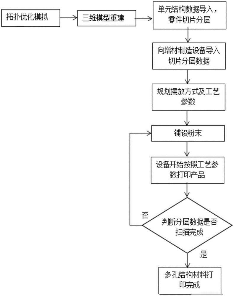
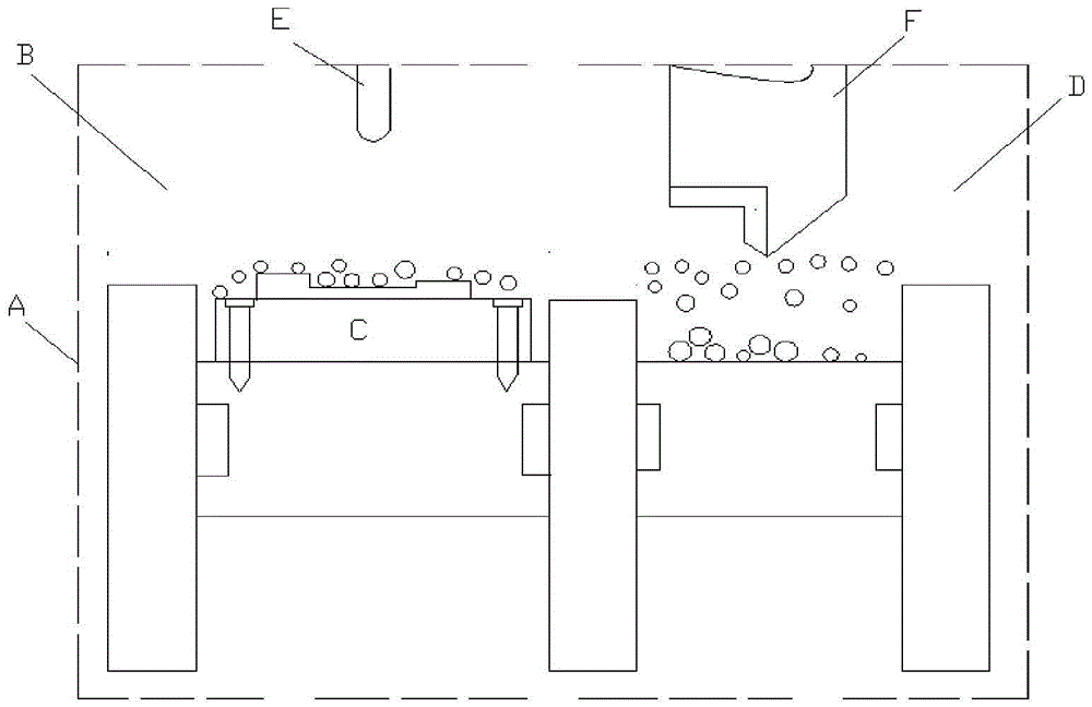
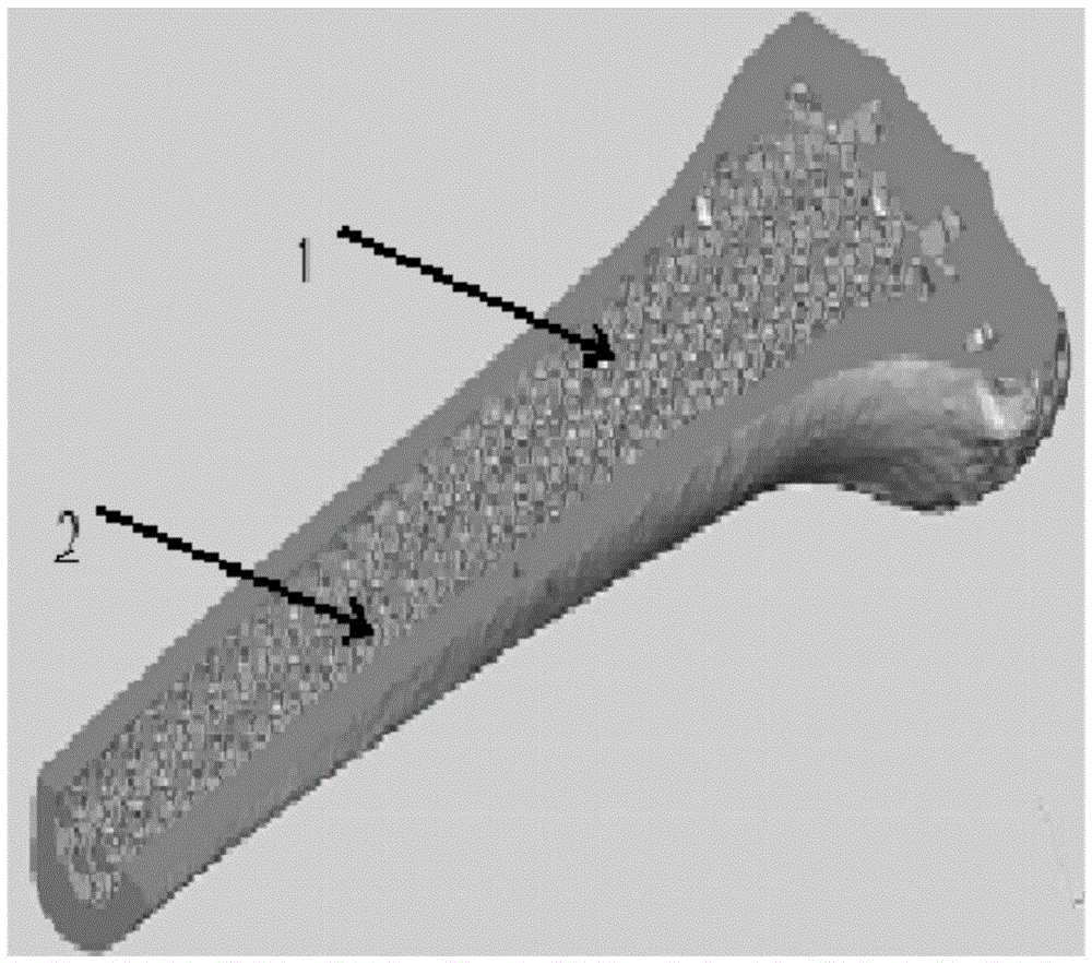

Image

  • Design and manufacturing method of porous grid structure material
  • Design and manufacturing method of porous grid structure material
  • Design and manufacturing method of porous grid structure material

Examples


Embodiment 1

[0033] A 3D printing manufacturing method for a porous implant skeleton. The additive manufacturing equipment adopts EOSM280, the supporting software is PSW3.5, and the material adopts EITi6al4v.

[0034] 1. According to the porous implanted bone model that needs to be manufactured, fill the core that needs to be filled into the topology-optimized porous unit grid structure of appropriate size. The support cannot be removed after the internal pores are formed, so the design should be adjusted reasonably to avoid increasing Internal support that is difficult to remove;

[0035] 2. Fill the ELITi6al4v powder into the M280 powder spreading tank;

[0036] 3. Use the software RP-Tools to slice and layer the three-dimensional graphics of porous bone implants, with a layer thickness of 10 μm; the obtained series of two-dimensional slice data are imported into the software EOSPSW3. Layer two-dimensional graphic laser scanning path and the use of process parameters; set the appropriat...

Embodiment 2

[0044] A porous unit grid structure, first by establishing a 20×20×20 cube model in the simulation software ANSYS, the upper right corner (20,20,20) is subjected to a concentrated load force, and the lower left corner (0,0,0) and its surroundings are fixed ends, input the elastic modulus and Poisson's ratio of the solid material itself without pores and the desired volume fraction. Divide the grid into 20 layers, set the topology optimization control process (ACCUR (accuracy) = 0.001, ITER (iterations) = 20) and solve to obtain the final density cloud map, and finally control the output density in the density cloud map to the red part above 0.8 . During the modeling process, the density cloud image is divided into 20-30 sections along the X-axis direction through the application software SolidWorks, and the images with a density exceeding 0.8 in the section density information are positioned and recorded by the drawing software, and finally staked out and connected until the m...


PUM

PropertyMeasurementUnit
thicknessaaaaaaaaaa

Abstract

The invention discloses a design and manufacturing method of a porous grid structure material and aims to solve the problems of blindness and uncertainty in traditional manufacturing of a porous material and apply an effective design concept for the porous material to practical manufacturing. The design and manufacturing method comprises the following steps: obtaining a data image based on topological optimization simulation; performing three-dimensional rebuilding on the data image on Solid Works; importing to magics software as a unit grid structure; filling into various three-dimensional models of specific parts which need to adopt the grid structure at any size ratio; afterwards manufacturing the parts. According to the design and manufacturing method, firstly, the three-dimensional model of each part is imported to a computer on a worktable; the printing angle and the printing position are set according to the three-dimensional graph structure; a powder layer is sintered into a corresponding two-dimensional shape on the layer; powder with the same thickness is repeatedly laid on the worktable on which one layer of graph is sintered; laser scanning is still performed according to the scanning route of the layer until the overall three-dimensional graph is completed. The design and manufacturing method disclosed by the invention has the advantages of reducing the elasticity modulus of the part and realizing good mechanical properties.

Description

technical field [0001] The invention relates to a design and manufacturing method of a porous structure material with an elastic modulus that can be freely adjusted and has an optimized unit structure and its unit topology optimization structure, belonging to the field of biomedicine. Background technique [0002] Medical metal implant materials are materials used to replace or repair normal human tissues and perform their physiological functions. They usually need to meet the following performance requirements: 1. Biocompatibility; 2. Excellent mechanical properties; 3. Low elasticity Modulus, 4 corrosion resistance and wear resistance. For a long time, medical metal implant materials mainly include stainless steel, CoCr alloy, Ti-based alloy, etc. The clinical application of medical metal implants originated from the osseointegration theory discovered by Mr. Branemark between 1952 and 1965. He expressed it this way: "expresses the phenomenon of direct growth contact betwe...

Claims


Application Information

Patent Timeline
Patent Type & Authority Applications(China)
IPC IPC(8): B22F3/11B33Y10/00A61L27/56A61L27/06A61L27/04
CPCA61L27/04A61L27/06A61L27/56A61L2430/02B22F3/11
Inventor 张冬云曹玄扬徐仰立谢印开
Owner BEIJING UNIV OF TECH
Why Eureka
Try Eureka