Optical wireless communication device and method applied in chaotic medium

A technology of optical wireless communication and medium, applied in the field of wireless optical communication, can solve the problems of optical wireless communication link interruption bit error rate, high cost of implementation, unfavorable practical application of wireless communication, etc., achieve low bit error rate, suitable for rapid deployment, The effect of low power consumption

Active Publication Date: 2017-10-24
NANJING UNIV OF SCI & TECH
View PDF11 Cites 0 Cited by
  • Summary
  • Abstract
  • Description
  • Claims
  • Application Information

AI Technical Summary

Problems solved by technology

For chaotic media (for example: bad weather, sea water, etc.), the number of ballistic photons and serpentine photons is very small. Will be interrupted (bit error rate is too high)
Researchers have proposed multiple ways to reduce these effects, including aperture averaging (Andrews L C. Aperture-averaging factor for optical scintillations of plane and spherical waves in the atmosphere[J].JOSAA.1992,9(4):597-600 .), adaptive optics (Zocchi F E.Asimple analytical model of adaptive optics for direct detection free-space optical communication[J].Optics communications.2005,248(4):359-374.), error correction coding (Chatzidiamantis N D ,Karagiannidis G K,Uysal M.Generalized maximum-likelihood sequence detection for photon-counting free space opticalsystems[J].Communications,IEEE Transactions on.2010,58(12):3381-3385.) and orbital angular momentum method (Alzubi J A, Alzubi O A, Chen T M. Forward Error Correction Based OnAlgebraic-Geometric Theory [M]. Springer, 2014.) and other technologies, but these methods are mainly aimed at reducing the bit error rate for weak channel interference, and the implementation cost is high, which is not conducive to Practical Applications of Wireless Communications

Method used


Image

  • Optical wireless communication device and method applied in chaotic medium
  • Optical wireless communication device and method applied in chaotic medium
  • Optical wireless communication device and method applied in chaotic medium

Examples


Embodiment

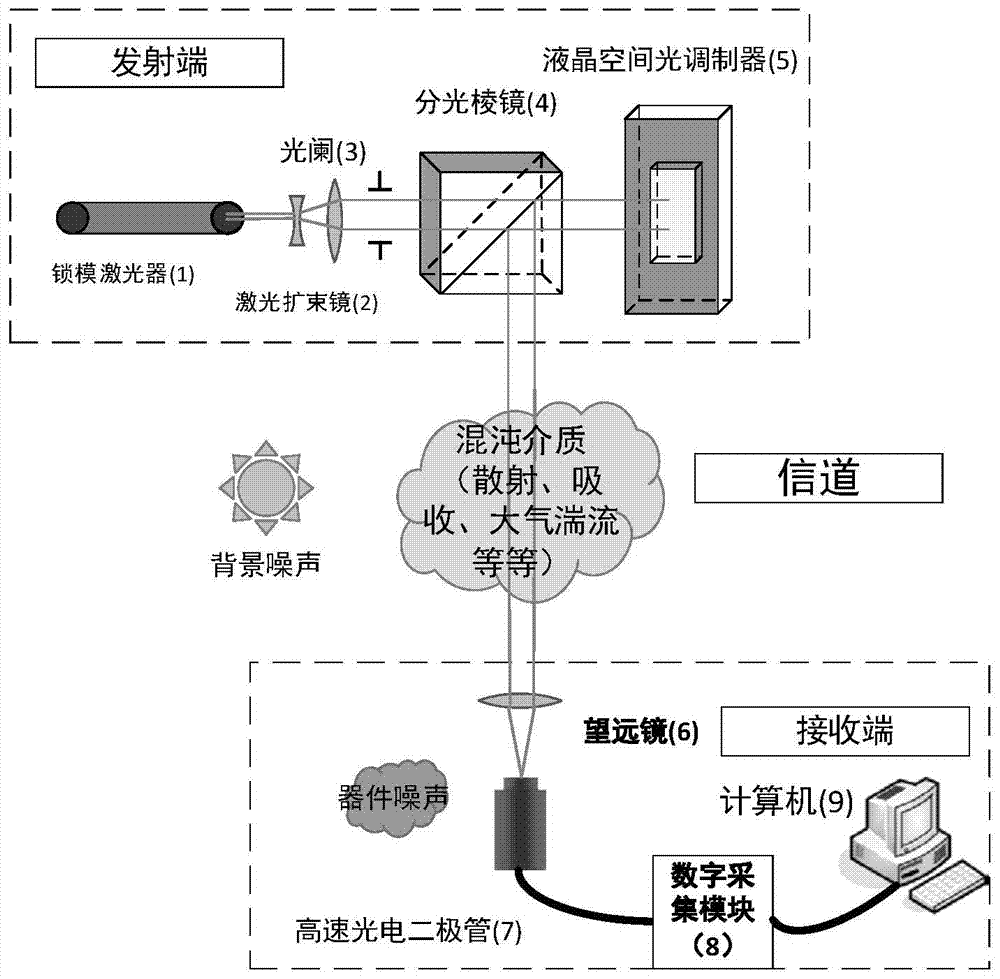
[0033] combine figure 1 , the present invention is applied to the optical wireless communication method in the chaotic medium, and the steps are as follows:

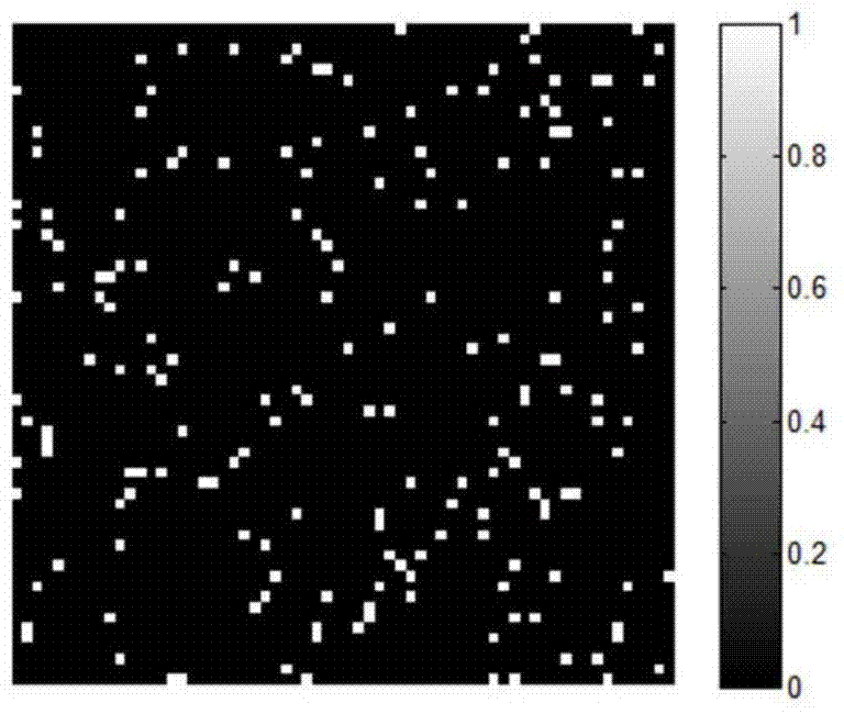
[0034] first step, such as figure 1 As shown, for the 64×64 experimental signal to be transmitted, use C++ to generate a 1500×4096 sampling matrix and import it into the memory of the digital micro reflective array DMD. According to the coding rules, the signal to be transmitted (as shown in Fig. 2(c)) for encoding.

[0035] The second step is to process the disturbance of the signal by the chaotic medium, and obtain the expression of the relationship between the signal at the receiving end and the signal at the transmitting end

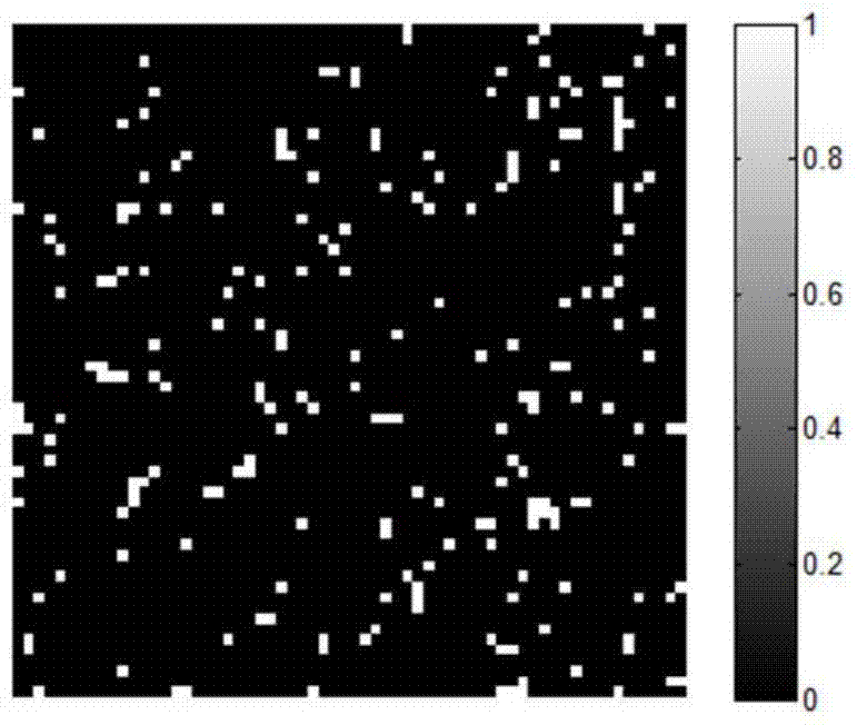
[0036] The third step is to construct the transmission equation y=λAx+e in the chaotic medium, and perform the spatial second-order correlation operation to obtain the signal transmission equation △=λΦx. Using convex optimization algorithm and CVX convex optimization toolkit, use Matlab ve...


PUM


Abstract

The invention discloses an optical wireless communication device and method applied to turbid media. The device comprises a mode-locked laser, a laser beam expander, a diaphragm, a beam splitter prism, a liquid crystal spatial light modulator, a telescope, a high-speed photodiode, a digital acquisition module and a computer, wherein the laser beam expander, the diaphragm, the beam splitter prism and the liquid crystal spatial light modulator are sequentially placed on the center axis of the output end of the mode-locked laser, and all optical centers are matched; the optical axes of the liquid crystal spatial light modulator and the telescope are crossed with each other; the high-speed photodiode is placed on a rear focal plane of the telescope; the signal output end of the high-speed photodiode is connected with the analog input end of the digital acquisition module by a coaxial cable, and the output end of the digital acquisition module is connected with a network port of the computer and uploads a data acquisition result. The method and the device can effectively inhibit the influence of turbid media on optical wireless communication, and realize communication with low bit error rate.

Description

technical field [0001] The invention belongs to wireless optical communication technology, in particular to an optical wireless communication device and method applied in a chaotic medium. Background technique [0002] Optical wireless communication, including free space optical-communication (FSO) and visible light communication (visible light communication, VLC), has a wide spectrum, high transmission rate, no need for spectrum certification, anti-electromagnetic interference, strong confidentiality, and easy Deployment and other advantages have been widely used and paid attention to in the military and commercial fields. At present, optical wireless communication is mainly a point-to-point transmission method, that is, a single-port photoelectric conversion module at the transmitting end emits encoded optical pulses, and the barrel detector at the receiving end obtains the pulses through the telescopic system, and decodes them through the back-end computing module. commu...

Claims


Application Information

Patent Timeline
Patent Type & Authority Patents(China)
IPC IPC(8): H04B10/11
CPCH04B10/11
Inventor 何伟基冒添逸邹云浩戴慧东陈钱顾国华张闻文钱惟贤隋修宝任侃路东明于雪莲
Owner NANJING UNIV OF SCI & TECH
Why Eureka
Try Eureka