Activated sludge treatment method and system for wastewater

A technology of activated sludge and treatment method, which is applied in the field of activated sludge treatment system for wastewater treatment, and can solve the problems of waste of air aeration energy consumption, etc.

Active Publication Date: 2016-05-11
CHINA PETROLEUM & CHEM CORP +1
View PDF3 Cites 19 Cited by
  • Summary
  • Abstract
  • Description
  • Claims
  • Application Information

AI Technical Summary

Problems solved by technology

This will inevitably lead to waste o

Method used


Image

  • Activated sludge treatment method and system for wastewater
  • Activated sludge treatment method and system for wastewater
  • Activated sludge treatment method and system for wastewater

Examples


Embodiment approach

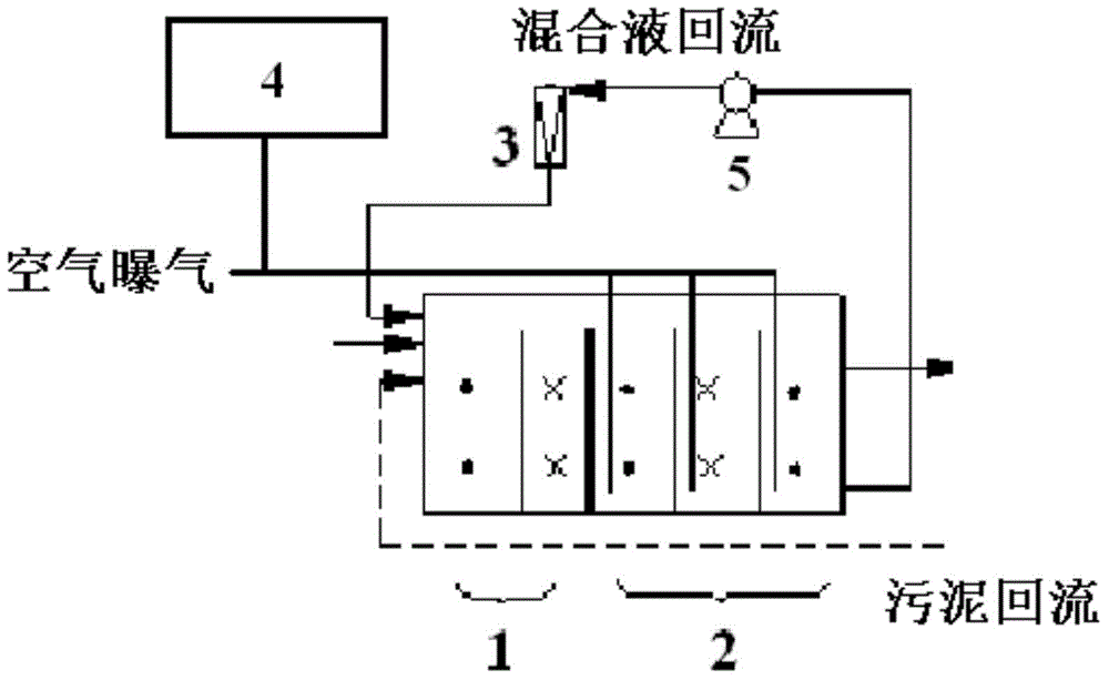
[0060] like figure 2As shown, according to another preferred embodiment of the present invention, the system further includes a carbon dioxide supply unit 4 communicated with the aerobic unit.

[0061] According to the present invention, the carbon dioxide supply unit is preferably a hydrogen production device. By connecting with the hydrogen production device, the gas discharged from the hydrogen production device can be supplied to the aerobic unit 2 through the carbon dioxide vent pipe. Thereby, the gas exhausted from hydrogen production is recovered and utilized, which is beneficial to the protection of the atmospheric environment.

[0062] According to the present invention, the system can also include a homogeneous unit and an air flotation separation unit arranged in sequence to realize the homogeneity and air flotation separation of wastewater. Aerobic unit 2 upstream.

[0063] According to a particularly preferred embodiment of the present invention, in actual use...

Embodiment 1-4

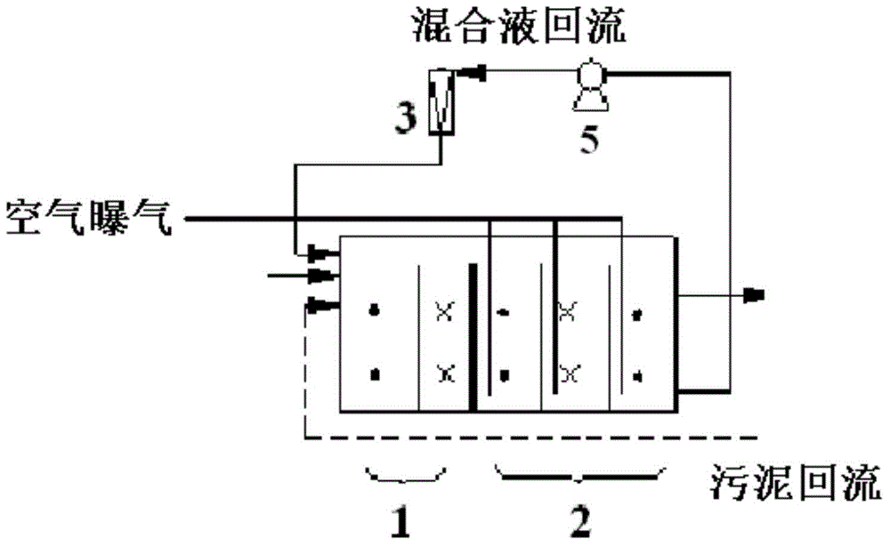
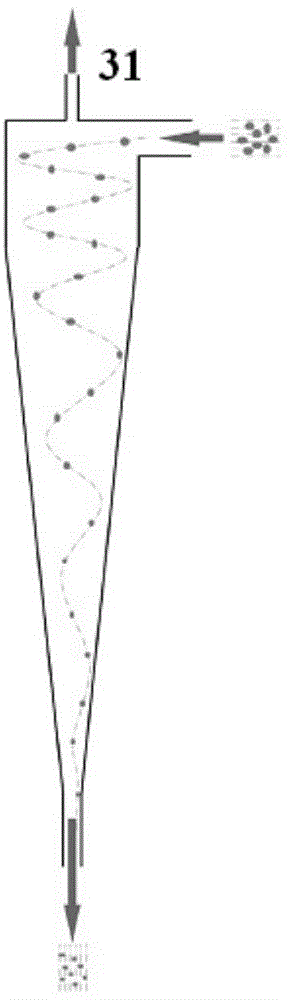
[0078] use figure 1 The shown device respectively carries out activated sludge treatment (including anoxic treatment and aerobic treatment) to electric desalination wastewater 1, saline wastewater 1, oily wastewater 1 and stripping wastewater 1. Pollution Control Engineering, Pages 342-344: Water Pollution Control Engineering, edited by Wang Yu, deputy editor by Lin Fengkai, Chemical Industry Press, 2008". The difference is that a cyclone is set on the return line from aerobic to anaerobic, the flow rate of the cyclone inlet is 4-6m / s, the feed pressure is 0.10-0.15MPa, the inlet and outlet The pressure difference of the cyclone is 0.10-0.15MPa, the flow rate of the overflow port of the cyclone is 3.5 volume% of the inlet flow rate, and the velocity gradient of the mixed material (reflux liquid) from the aerobic treatment in the cyclone is 4000S -1 . The particle size of 80% by weight of activated sludge flocs after cyclone is 0.5-1mm, and the particle diameter of all activa...

Embodiment 5-8

[0080] use figure 1 The shown device performs activated sludge treatment (including anoxic treatment and aerobic treatment) on electric desalination wastewater 2 , saline wastewater 2 , oily wastewater 2 and stripping wastewater 2 respectively. The treatment method is carried out according to ""Water Pollution Control Engineering" pages 342-344: Water Pollution Control Engineering, editor-in-chief Wang Yu, deputy editor-in-chief Lin Fengkai, Chemical Industry Press, 2008". The difference is that a cyclone is set on the return line from aerobic to anaerobic, the flow rate of the cyclone inlet is 1-4m / s, the feed pressure is 0.03-0.06MPa, the inlet and outlet The pressure difference of the cyclone is 0.06MPa, the flow rate of the overflow port of the cyclone is 2% by volume of the inlet flow rate, and the velocity gradient of the mixed material (reflux liquid) from the aerobic treatment in the cyclone is 2800S -1 . The particle size of 60% by weight of activated sludge flocs a...


PUM


Abstract

The invention discloses an activated sludge treatment method for wastewater. The method comprises the following steps that 1, under the anoxic treatment condition, the wastewater makes contact with a material containing activated sludge, and anoxic treatment on the wastewater is performed; 2, aerobiotic treatment is performed on a mixture obtained after the contact; 3, part of a mixed material obtained through aerobiotic treatment is returned to the step 1 to serve as part of the material containing the activated sludge, wherein the particle size of at least 60 wt% of the activated sludge in the mixed material which is obtained through aerobiotic treatment and returned to the step 1 is not larger than 1 mm. The invention further provides an activated sludge treatment system for the wastewater. According to the activated sludge treatment method and system for the wastewater, the degradation and nitrification efficiency of organic matter difficult to degrade in the wastewater is promoted, and agentia feeding and O pool aeration strengthening are not needed; the advantages of being low in operation cost and free of by-products are achieved.

Description

technical field [0001] The invention relates to an activated sludge treatment method for wastewater and an activated sludge treatment system for wastewater treatment. Background technique [0002] The existing relatively mature wastewater treatment technology generally adopts a combined treatment process of single-stage or two-stage air flotation and activated sludge. The A / O (anoxic / aerobic) process has always been the preferred process for wastewater biological treatment due to its advantages of stable operation, simple operation and maintenance, and effective denitrification. [0003] Taking the oily wastewater from an oil refinery as an example, the content of petroleum substances is as high as 500mg / L or above. After multi-unit oil removal pretreatment, the raw water entering the A / O process still contains a certain amount of colloidal dispersed oil and emulsified oil. There will be situations where these tiny oil droplets are adsorbed and coated on the activated sludg...

Claims


Application Information

Patent Timeline
IPC IPC(8): C02F3/30
Inventor 陈秀荣汪华林刘毅杨雪晶施俊林余水龙俞惠庆
Owner CHINA PETROLEUM & CHEM CORP
Why Eureka
Try Eureka