Cleaning apparatus and method for ultrahigh vacuum chamber

An ultra-high vacuum, cleaning device technology, used in electrical components, semiconductor/solid-state device manufacturing, circuits, etc., can solve problems such as damage to electronic components, potential safety hazards, and large temperature gradients, and achieve the effect of long degassing time.

Active Publication Date: 2016-05-11
SHANGHAI MICRO ELECTRONICS EQUIP (GRP) CO LTD
View PDF5 Cites 8 Cited by
  • Summary
  • Abstract
  • Description
  • Claims
  • Application Information

AI Technical Summary

Problems solved by technology

[0010] This cleaning method cleans the sample in a high-concentration oxygen, argon and hydrogen environment, and the cleaning can achieve the effect required by the general process technology, but this method cannot accurately determine whether the pollutants on the sample surface have been effectively removed, and the cleaning time depends on experience Judgment; the use of high concentrations of oxygen and hydrogen has potential safety hazards; the electric heating and baking inner chamber may damage some delicate electronic components due to the large temperature rise gradient

Method used


Image

  • Cleaning apparatus and method for ultrahigh vacuum chamber
  • Cleaning apparatus and method for ultrahigh vacuum chamber
  • Cleaning apparatus and method for ultrahigh vacuum chamber

Examples


Embodiment 1

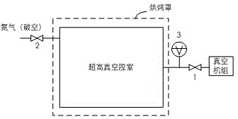
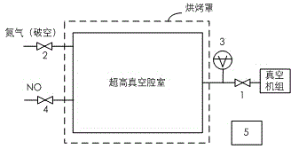
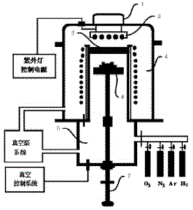
[0046] Such as Figure 5 as shown, Figure 5 It is a structural schematic diagram of the cleaning device used in the ultra-high vacuum chamber of the present invention. The cleaning device of the present invention mainly includes the following components: an ultra-high vacuum chamber, and an ultra-high vacuum chamber with pollutants attached to its inner wall, that is, the object to be cleaned. The vacuum unit is used to evacuate the ultra-high vacuum chamber to make the chamber reach an ultra-high vacuum state. Vacuum valves 1, 2, and 4 are valves for on-off gas and UV light. Vacuum gauge 7, tests the degree of vacuum in the chamber. Quadrupole mass spectrometer 6, to test the partial pressure of pollutants in the chamber (the atomic mass unit AMU range is 0-300). Inert gas, ionized under ultraviolet light, bombards the inner surface of the cavity to remove pollutants. The ultraviolet UV light source 5 is used to irradiate the inert gas to make it ionized (wavelength 100...

Embodiment 2

[0073] In another embodiment of the present invention, 10% oxygen is added to the gas source.

[0074] During cleaning, a small amount of inert gas (one or more of He / Ne / Ar / Kr / Xe) is injected in an ultra-high vacuum state, and the partial pressure of the inert gas can be tested by a vacuum gauge and then transmitted to the automatic pressure controller. The controller compares this value with the previously set threshold, and if it is lower than the threshold, the opening of the fine-tuning valve will be increased, otherwise, the opening will be decreased. After a certain wavelength of UV light irradiates the inert gas atoms, the atoms are ionized and bombard the inner wall of the cavity, see reaction formula (1), and the hydrocarbons adhering to the cavity wall are dissociated and become gaseous hydrocarbons, see Reaction formula (2). Gaseous hydrocarbons are pumped out of the chamber by the vacuum unit. Adding 10% oxygen can dissociate strong oxidizing ozone molecules and ...

Embodiment 3

[0080] In a third embodiment of the present invention, 10% of water vapor is used instead of 10% of oxygen.

[0081] During cleaning, a small amount of inert gas (one or more of He / Ne / Ar / Kr / Xe) is injected in an ultra-high vacuum state, and the partial pressure of the inert gas can be tested by a vacuum gauge and then transmitted to the automatic pressure controller. The controller compares this value with the previously set threshold, and if it is lower than the threshold, the opening of the fine-tuning valve will be increased, otherwise, the opening will be decreased. After a certain wavelength of UV light irradiates the inert gas atoms, the atoms are ionized and bombard the inner wall of the cavity, see reaction formula (1), and the hydrocarbons adhering to the cavity wall are dissociated and become gaseous hydrocarbons, see Reaction formula (2). Gaseous hydrocarbons are pumped out of the chamber by the vacuum unit.

[0082] After water vapor enters the vacuum chamber, a ...


PUM


Abstract

The invention relates to a cleaning apparatus and method for an ultrahigh vacuum chamber. The cleaning apparatus comprises an ultraviolet light source, a control device, a vacuum pump system and a cleaning gas source. The cleaning apparatus is characterized in that the cleaning apparatus further comprises a quadrupole mass spectrograph used for testing the partial pressure of pollutants in the chamber, a vacuum gauge used for performing real-time monitoring on vacuum degree in the chamber, a pressure intensity control instrument, a fine adjustment valve, a cold plate and a temperature control unit; the pressure intensity control instrument controls the opening degree of the fine adjustment valve and accurately controls the partial pressure of a cleaning gas in the vacuum cleaning chamber; circulating water is led into the cold plate, so that the temperature of the outer wall of the chamber can be controlled through water temperature; and the temperature control unit provides circulating water with stable temperature. The invention also discloses a cleaning method for an ultrahigh vacuum chamber.

Description

technical field [0001] The invention relates to a cleaning device and method for an ultra-high vacuum chamber. Background technique [0002] Ultra-high vacuum systems are often used in technical fields such as vacuum coating machines, molecular beam epitaxy equipment, particle accelerators, and material surface treatment. The vacuum degree of the ultra-high vacuum system is E-7~E-10Pa. When the ultra-high vacuum system is used for a long time or exposed to the atmosphere for a short time, pollutants will adhere to the inner wall of the vacuum chamber. From the perspective of chemical characteristics, it can be inorganic or organic. The attached pollutants will seriously affect the vacuum degree of the vacuum system, so the vacuum system needs to be degassed and cleaned. [0003] The common cleaning method is heating and baking, such as figure 1 As shown, a baking hood is added outside the vacuum system, and the baking hood is energized to heat the vacuum chamber, and the ...

Claims


Application Information

Patent Timeline
Patent Type & Authority Applications(China)
IPC IPC(8): H01L21/02H01L21/67
Inventor 俞芸
Owner SHANGHAI MICRO ELECTRONICS EQUIP (GRP) CO LTD
Why Eureka
Try Eureka