
Air shockwave crushing sludge drying device and sludge shockwave drying system

A sludge drying and air shock technology, applied in water/sludge/sewage treatment, sludge treatment, dehydration/drying/concentrated sludge treatment, etc. and other problems to achieve the effects of avoiding investment costs, low energy consumption, and avoiding odors

Inactive Publication Date: 2016-06-01
JIANGSU ZHAOSHENG ENVIRONMENTAL PROTECTION TECH CO LTD
View PDF9 Cites 44 Cited by
  • Summary
  • Abstract
  • Description
  • Claims
  • Application Information

AI Technical Summary

Problems solved by technology

At present, common mechanical drying equipment such as three-way rotary circular dryer, belt dryer, paddle dryer, disc dryer, fluidized bed dryer, etc., these dryers use mechanical means to stir and squeeze sludge pressure, not only consumes a lot of energy, but also makes it difficult for the packaged water to break through the wall and flow out
Another type of airflow drying equipment needs to heat the air entering the equipment, and use the heat of the air to evaporate water. The energy consumption of the heating equipment is very high. If the heat energy needs to be recovered, a larger gas-phase and gas-phase heat exchanger is required. The equipment investment cost is also relatively high; at the same time, due to the entry of hot air, the organic volatiles in the sludge will be more likely to overflow, and a large amount of odor will be generated, resulting in more tail gas treatment equipment, which increases the equipment cost; and the above The airflow drying equipment also has the disadvantage that it is difficult to evaporate the water wrapped in the sludge

Method used


Image

  • Air shockwave crushing sludge drying device and sludge shockwave drying system
  • Air shockwave crushing sludge drying device and sludge shockwave drying system
  • Air shockwave crushing sludge drying device and sludge shockwave drying system

Examples


Embodiment Construction

[0021] The specific implementation manner of the present invention will be described below in conjunction with the accompanying drawings.

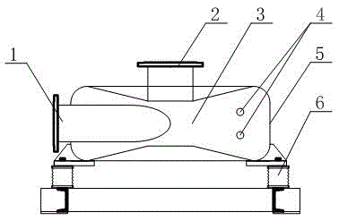
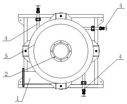
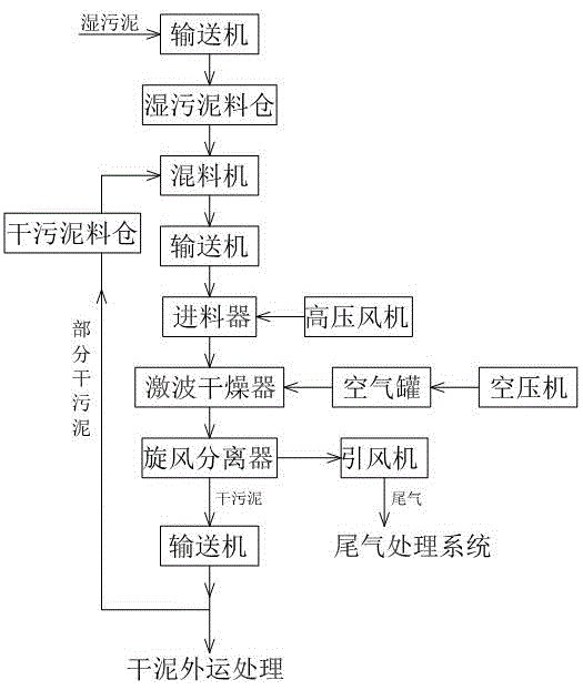
[0022] Such as figure 1 As shown, the housing 5 of the air shock wave crushing sludge dryer of the present invention is fixed on the bottom shock-absorbing frame through the rubber pad 6, and the housing 5 is a flat cylinder, such as figure 2 As shown, the shell 5 is respectively provided with a feeding port 1 and three sets of compressed air injection pipes 4 in four tangential directions, and each set of compressed air injection pipes 4 is composed of upper and lower two injection pipes 4 with Laval nozzles , the discharge port 2 is arranged on the central top of the housing 5, the inside of the housing 5 is a cavity 3 with a thicker periphery and a thinner center similar to a persimmon shape, the feed port 1, the discharge port 2 and the injection pipe 4 are all connected The cavities 3 are connected. According to different system de...


PUM


Abstract

The invention discloses an air shockwave crushing sludge drying device of which the shell is cylindrical. The shell is at least provided with a feed port and a set of compressed air injection pipes in the tangential direction, wherein each compressed air injection pipe is provided with a Laval nozzle; a discharge port is arranged at the central top of the shell; the inside of the shell is provided with a cavity; and a feed port, the discharge port and the injection pipes respectively communicate with the cavity. The normal-temperature air is utilized, thereby avoiding the investment cost on high-energy-consumption heating equipment and large-size heat-exchange equipment, and preventing the odor from generation. The shape of the cavity conforms to the mechanical characteristics of hydromechanics; and the high-speed air flow is utilized to carry the sludge to rotate and mutually collide at high speed in the cavity, thereby effectively pulverizing the sludge. The compressed air shockwaves generated by the Laval nozzle are utilized to impact the suspended sludge particles moving at high speed in the cavity; the unit-cell-coated water is subjected to wall breaking, and the water is atomized and vaporized at normal temperature; and thus, the drying device has the advantage of low energy consumption and can complete the sludge drying efficiently.

Description

technical field [0001] The invention relates to the field of environmental protection equipment, in particular to an air shock wave crushing sludge dryer and a sludge shock drying system. Background technique [0002] The water content of the remaining sludge in sewage treatment plants is relatively high, usually reaching 95-99%. There are often a large number of fungi, cells and other organic organisms in this biochemical sludge, and its own cell membrane wraps a large amount of water. This crystal Cell-enclosed water is difficult to break the wall. At present, common mechanical drying equipment such as three-way rotary circular dryer, belt dryer, paddle dryer, disc dryer, fluidized bed dryer, etc., these dryers use mechanical means to stir and squeeze sludge Pressure not only consumes a lot of energy, but also makes it difficult for the packaged water to break through the wall and flow out. Another type of airflow drying equipment needs to heat the air entering the equip...

Claims


Application Information

Patent Timeline
IPC IPC(8): C02F11/12C02F11/00B02C19/06
CPCC02F11/12B02C19/061B02C2201/06C02F11/00
Inventor 周震球尹志强荣杰尹曙辉钱登
Owner JIANGSU ZHAOSHENG ENVIRONMENTAL PROTECTION TECH CO LTD
Learn More