Semi-closed two-chamber anaerobic reaction device and wastewater treatment method thereof

An anaerobic reaction device, semi-closed technology, applied in anaerobic digestion treatment, biological treatment devices, chemical instruments and methods, etc., can solve the problems of slow start-up speed, uniform water distribution, complex structure, etc. The effect of increasing the probability of contact and improving the processing effect

Active Publication Date: 2016-06-22
南京简迪环境工程有限公司
View PDF10 Cites 2 Cited by
  • Summary
  • Abstract
  • Description
  • Claims
  • Application Information

AI Technical Summary

Problems solved by technology

The reactor adopts a variable-diameter design with the bottom big and the top small, which reduces the diameter of the upper reaction chamber and the three-phase separation. Although the manufacturing materials are saved, it is easy to cause the following problems: the upward flow rate in the upper part increases suddenly, which makes the separation of mud and water poor; the upper surface area Sudden reduction can easily lead to biased flow or local turbulence affecting the effect of three-phase separation; the problem of water distribution is not fundamentally solved, although it can prevent clogging, it is still prone to problems such as uniform water distribution
The reactor is fed with water through the nozzle and continuously transferred from the pipeline to several sub-reaction chambers in series. Although the mud-water mixing effect is relatively sufficient, the structure is complicated. The biggest problem is that it is easy to block and requires high energy consumption for transfer.
Therefore, the current anaerobic reaction device has the problems of uneven water distribution, slow start-up speed, difficult operation and maintenance, and low efficiency.

Method used


Image

  • Semi-closed two-chamber anaerobic reaction device and wastewater treatment method thereof
  • Semi-closed two-chamber anaerobic reaction device and wastewater treatment method thereof
  • Semi-closed two-chamber anaerobic reaction device and wastewater treatment method thereof

Examples


Embodiment 1

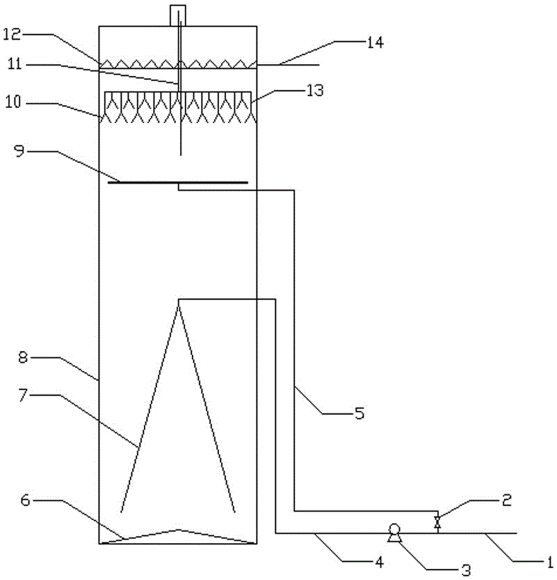
[0025] Example 1: The invention provides a semi-enclosed two-chamber anaerobic reaction device, the schematic diagram of which is as follows figure 1 As mentioned above, its basic device includes a main reactor 8 and a water inlet system. The water pump 3 is connected between the front pipe 1 of the water inlet pump and the water inlet pipe 4 , and the other end of the water inlet pipe 4 leads into the main reactor 8 . The main reactor 8 is the main pool wall of the anaerobic reactor, mostly cylindrical in shape, steel concrete or steel structure, with anti-corrosion measures on the inner wall, and generally an insulating layer on the outside. The water inlet system includes the water inlet pipe 4, the front pipe 1 of the water inlet pump and the water pump 3. The rated flow rate of the water pump 3 is 2-4 times of the designed water inlet, and the head is determined according to the liquid level height of the reactor. On the basis of this structure, the present invention is ...

Embodiment 2

[0041] Example 2: The present invention provides a semi-enclosed two-chamber anaerobic reaction device, the structure of which is basically the same as in Example 1, the difference being that the apex angle of the central cone is 45°, the diameter of the distribution main pipe is 250 mm, and the three-phase separator layer The spacing is 200mm, and steel plates and anti-corrosion measures are used.

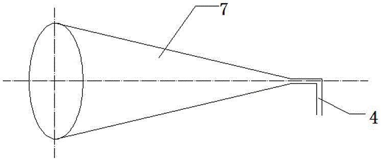
[0042] In the process of wastewater treatment in this embodiment, the flow velocity at the outlet at the top of the central cone is 6.7m / s, the descending flow velocity at the bottom of the central cone is 7.3m / h, and the flow velocity at the bottom of the pool is 20.2m / h. The ascending flow rate in the main reactor is 5.2m / h.

[0043] The anaerobic reaction device and the wastewater treatment process in this example are applied to the wastewater in the production of a food enterprise. The pH of the wastewater is 7.2; SS: 3600-8500mg / L; COD: 16500-23000mg / L, which is high concen...

Embodiment 3

[0044] Example 3: The present invention provides a semi-enclosed two-chamber anaerobic reaction device, the structure of which is basically the same as in Example 1, the difference being that the apex angle of the central cone is 35°, the diameter of the distribution main pipe is 300mm, and the three-phase separator layer The spacing is 180mm.

[0045] In the process of wastewater treatment in this embodiment, the flow velocity at the outlet at the top of the central cone is 8.5m / s, the descending flow velocity at the bottom of the central cone is 6.6m / h, and the flow velocity at the bottom of the pool is 25.4m / h. The rising velocity in the main reactor is 4.8m / h.

[0046] The anaerobic reaction device and the process of treating waste water in this example are applied to the waste water in the production of a certain pharmaceutical company. The pH of the waste water: 7-9; SS: 1200-3600mg / L; COD: 9600-14300mg / L, which is high Concentrated organic wastewater has a certain bi...


PUM

PropertyMeasurementUnit
angleaaaaaaaaaa

Abstract

The invention provides a semi-closed two-chamber anaerobic reaction device. The semi-closed two-chamber anaerobic reaction device comprises a main reactor and a water inlet pipe and is characterized by further comprising a center cone and a bottom cone, wherein the center cone is a bottom-cover-free cone structure; the cone angle is 20-50 degrees; the center cone is fixed at a lower middle part of the main reactor; the top end of the center cone is communicated with the water inlet pipe; the bottom cone is arranged right under the center cone; the bottom cone is of a cone structure; the bottom surface of the bottom cone is superposed with the bottom surface of the main reactor; the cone angle is 140-160 degrees; central axes of the main reactor, the center cone and the bottom cone are superposed to form a semi-closed two-chamber structure. Through the semi-closed two-chamber anaerobic reaction device, the movement path of wastewater in the reactor is extended, so that the contact probability of the wastewater and sludge is increased; the treatment effect of the wastewater is improved; the uniform reflux sludge water is provided, so that the reactor runs in a stable state.

Description

technical field [0001] The invention relates to an anaerobic reaction device, more specifically to a semi-closed two-chamber anaerobic reaction device and a method for treating wastewater, belonging to the field of wastewater treatment. Background technique [0002] In recent years, due to the rapid development of industry and agriculture, a small amount of organic wastewater with high concentration and a large amount of agricultural or mixed domestic sewage with low concentration of organic matter and unbalanced nutrition have a greater destructive effect on the environment. In terms of resistance to water quality fluctuations, toxicity inhibition, and low-concentration organic wastewater treatment, it has become a major problem that anaerobic technology needs to be overcome in the wide application. Existing anaerobic reactors have problems such as low effective volume utilization, long start-up period, low water quality fluctuation resistance, uneven water distribution, et...

Claims


Application Information

Patent Timeline
Patent Type & Authority Applications(China)
IPC IPC(8): C02F3/28
CPCC02F3/2866C02F2203/006C02F2301/046
Inventor 赵杰郭孝虎顾行祥丁新春
Owner 南京简迪环境工程有限公司
Why Eureka
Try Eureka