Thermoelectric power generation energy storage and power transmission system applied to boiler economizer

A technology of thermoelectric power generation and power transmission system, which is applied to generators/motors, battery circuit devices, current collectors, etc., can solve the problems of large irreversible losses, low efficiency, and poor unit economy, and achieve high power generation and heat absorption. Faster, lower energy loss effect

Inactive Publication Date: 2016-06-22
SHANGHAI UNIVERSITY OF ELECTRIC POWER
View PDF3 Cites 2 Cited by
  • Summary
  • Abstract
  • Description
  • Claims
  • Application Information

AI Technical Summary

Problems solved by technology

Traditional fossil fuels are usually very inefficient in the process of power generation, and a large amount of energy loss exists in the boiler part in the rankine cycle of the power plant, which is caused by the temperature difference between the high temperature flue gas temperature and the high pressure steam temperature
Because the combustion temperature in the modern coal-fired power plant boiler boiler furnace is as high as 1700°C, and the temperature of the high-temperature and high-pressure heating surface is generally below 600°C, the temperature difference between the smoke temperature and the working fluid in the heating surface in different areas of the furnace is as high as 1000°C. There is also a temperature difference of 200-300°C in the economizer area. According to the second law of thermodynamics, the greater the heat transfer temperature difference, the greater the irreversible loss. The greater the loss, the worse the economy of the unit

Method used


Image

  • Thermoelectric power generation energy storage and power transmission system applied to boiler economizer
  • Thermoelectric power generation energy storage and power transmission system applied to boiler economizer
  • Thermoelectric power generation energy storage and power transmission system applied to boiler economizer

Examples


Embodiment

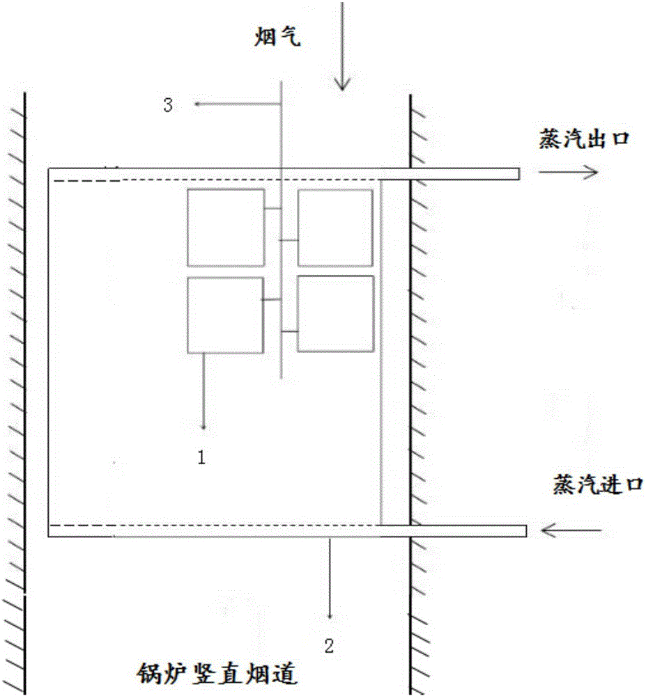
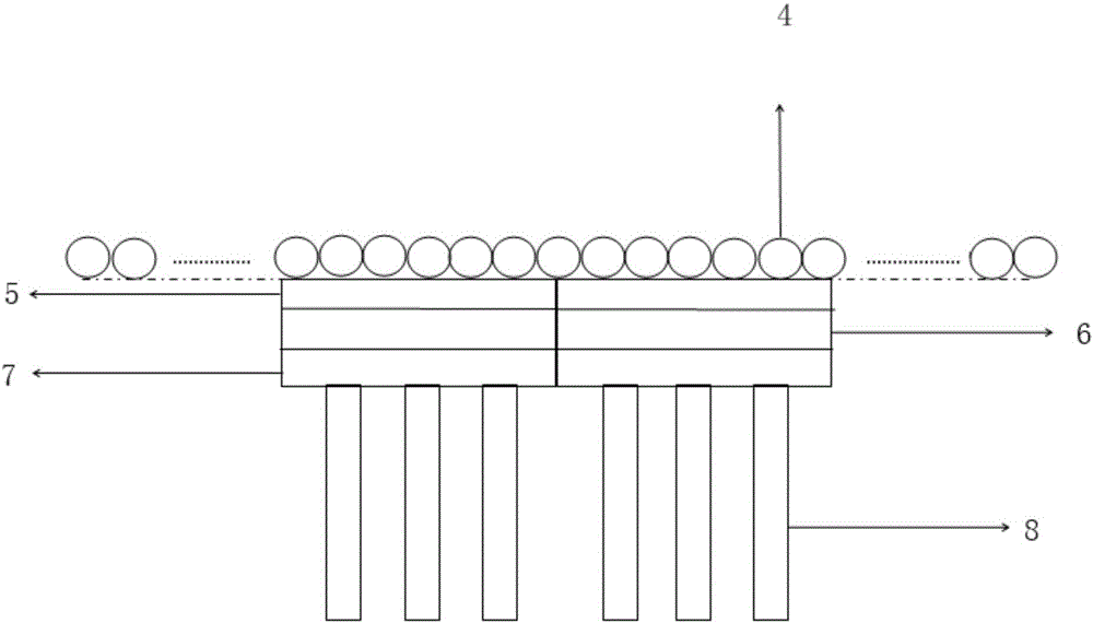
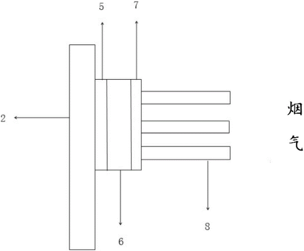
[0028] Such as Figure 1-4 As shown, a thermoelectric power generation energy storage and power transmission system applied to a boiler economizer, the system is set in the boiler furnace, including a thermoelectric power generation device 9, an energy storage device and a power transmission device, and the thermoelectric power generation device 9 includes a plurality of thermoelectric power generation devices Unit 1, a plurality of thermoelectric power generation units 1 are respectively connected to the energy storage device and the power transmission device through wires 3, the hot end of the thermoelectric power generation unit 1 is in contact with the high-temperature flue gas in the vertical flue of the boiler, and the cold end is in contact with the boiler economizer 2 ;

[0029] When the system is generating electricity, the thermoelectric power generation unit 1 uses the energy generated by the high-temperature flue gas in the vertical flue of the boiler as the hot en...


PUM


Abstract

The invention relates to a thermoelectric power generation energy storage and power transmission system applied to a boiler economizer, including a thermoelectric power generation device, an energy storage device and a power transmission device. The thermoelectric power generation device includes a plurality of thermoelectric power generation units, and the plurality of The thermoelectric power generation unit is respectively connected to the energy storage device and the power transmission device through wires. The thermoelectric power generation device is installed on the boiler economizer, and the hot end of the thermoelectric power generation unit is in contact with the hot flow flue gas of the vertical flue of the boiler, and the cold end In contact with the boiler economizer, the energy storage device and power transmission device are arranged outside the boiler. Compared with the prior art, the present invention has the advantages of improving power generation efficiency, increasing heat absorption rate, improving heat transfer efficiency, providing high-voltage direct and alternating current, fully Take advantage of other advantages.

Description

technical field [0001] The invention relates to the technical field of heat transfer enhancement and energy saving and emission reduction, in particular to a thermoelectric power generation energy storage and power transmission system applied to a boiler economizer. Background technique [0002] Thermoelectric power generation uses the Seebeck effect to convert the heat energy generated by the temperature difference between high temperature and low temperature into electric energy, but the electric energy directly generated is DC voltage. If it is stored, it needs to be adjusted by a voltage stabilizer protector before it can be stored; if it is used for transmission, it needs The power supply can only be supplied after being adjusted by the inverter and the voltage regulator protector in turn. [0003] Such as Figure 5 As shown, the picture is a structural schematic diagram of an existing power plant generating power based on the Rankine cycle principle. Conventional foss...

Claims


Application Information

Patent Timeline
Patent Type & Authority Applications(China)
IPC IPC(8): H02J7/32H02N11/00
CPCH02J7/32H02N11/002
Inventor 潘卫国尤运姜未汀王文欢
Owner SHANGHAI UNIVERSITY OF ELECTRIC POWER
Why Eureka
Try Eureka