Aluminum Alloy Ultrasonic Resistance Composite Butt Brazing Method

A brazing method and aluminum alloy technology, which is applied in the field of aluminum alloy brazing, can solve the problems that the welding current passes through the workpiece and the test bench, the base, affects the welding process parameters, and the welding joint area is small, so as to achieve compact structure and improve joint welding. The combination rate and the effect of improving the strength of welded joints

Inactive Publication Date: 2019-02-15
LANZHOU UNIVERSITY OF TECHNOLOGY
View PDF6 Cites 0 Cited by
  • Summary
  • Abstract
  • Description
  • Claims
  • Application Information

AI Technical Summary

Problems solved by technology

However, under the welding process of high current and short time, it is easy to cause problems such as welding current passing through the workpiece, test bench, base, etc., resulting in welding failure
When welding, simply apply pressure through the upper and lower electrodes of the resistance welding machine to compress the two overlapped workpieces, which will easily cause obvious indentations on the surface of the workpieces, and the welding joint area is small, which directly affects the welding strength.
[0007] In the existing ultrasonic-assisted resistance brazing device, the workpieces adopt overlapping welding joints, and the ultrasonic horn exerts pressure on the upper workpiece and the lower workpiece, but this welding method is easy to cause the pressure between the upper and lower workpieces Inaccurate, affecting welding process parameters, ultrasonic waves are input to the brazing seam through the workpiece

Method used


Image

  • Aluminum Alloy Ultrasonic Resistance Composite Butt Brazing Method
  • Aluminum Alloy Ultrasonic Resistance Composite Butt Brazing Method
  • Aluminum Alloy Ultrasonic Resistance Composite Butt Brazing Method

Examples


Embodiment 1

[0028] As shown in Figures 4-6, the insulating sliding welding device of the present invention includes a sliding part, an insulating part and a base 1. The base 1 and the guide rail 2 are connected by bolts. The sliding part includes the guide rail 2, the upper slider 3 and the lower slider 3'. There are the upper slider 3 and the lower slider 3' on the guide rail 2. The right surfaces of the sliders 3 and 3' m 3 Flat, with substrate 1 right surface M 1 parallel. The insulating part comprises an upper insulating plate 4, a lower insulating plate 4' and an insulating cap 6, and the axis OO' of the insulating cap 6 is connected to the right surface M of the insulating plate 4 4 The face is vertical.

[0029] In the above insulated sliding welding device, the upper slider 3 and the lower slider 3' are respectively provided with four positioning internal threads, and the upper workpiece 5, the upper insulating plate 4, the lower workpiece 5', and the lower insulating plate are...

Embodiment , Embodiment 2

[0033] Embodiment of the method of the present invention, embodiment 2: the resistance brazing of aluminum alloy:

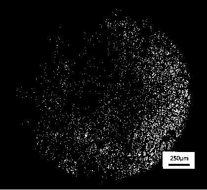
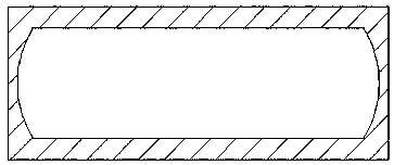
[0034] Such as figure 1 , figure 2 , image 3 , Figure 4 As shown, the aluminum alloy end face is processed, and the base metal is installed on the figure 2 On the jig shown, bolt the electrode to the base metal. Use sheet-shaped brazing filler metal to be placed in the groove to be welded, and the thickness of the brazing filler metal is 0.3mm. Set the resistance brazing parameters, the welding current is 2.5kA in the first stage, the welding time is 50CYC, the ultrasonic wave is applied for 6s, the welding pressure is 1MPa, the resistance brazing is started, and then the weldment is allowed to cool naturally.

[0035] The material is aluminum alloy, the end face size is 8×20mm, the groove depth is 0.15mm, and the solder is Al-Si-Mg (mass percentage: Si: 9-10.5% Mg: 1-2% Cu, Ni≤0.45% ), the thickness is 0.3mm, and the size is 6×16mm.

[0036]figure 1 S...

Embodiment , Embodiment 3

[0037] Embodiment of the method of the present invention, embodiment 3: the resistance brazing of aluminum alloy:

[0038] Such as figure 2 As shown, the aluminum alloy end face is processed, the base metal is installed on the fixture, and the electrode and the base metal are connected with bolts. The sheet-shaped brazing material is placed in the groove to be welded, and the thickness of the brazing material is 1mm. Set the parameters of resistance brazing. The welding current in the first stage is 2.5kA, the welding time is 50CYC, and the power is stopped for 50CYC. Resistance brazing followed by allowing the weldment to cool naturally.

[0039] The base material is aluminum alloy, the end face size is 8×30mm, the groove depth is 0.5mm, and the solder is Al-Si-Mg (mass percentage: Si: 9-10.5% Mg: 1-2% Cu, Ni≤ 0.45%), the thickness is 1mm, and the size is 6×16mm.


PUM

PropertyMeasurementUnit
thicknessaaaaaaaaaa
thicknessaaaaaaaaaa
thicknessaaaaaaaaaa

Abstract

The invention discloses an ultrasonic resistance composite butt brazing method for an aluminum alloy and an insulated sliding welding device. The ultrasonic resistance composite butt brazing method comprises the following steps of processing an aluminum alloy end surface, mounting parent metal on the insulated sliding welding device, and connecting an electrode and the pare metal by using bolts; placing flaky brazing filler metal in a to-be-welded groove, wherein the thickness of the flaky brazing filler metal is 0.1 to 1mm; setting resistance brazing parameters: setting welding current at a first stage to 2 to 2.5KA, welding time to 10 to 50CYC, welding current at a second stage to 3 to 9.5KA and welding time to 750 to 1500CYC, wherein ultrasonic waves are applied in the process, and the welding pressure is 150 to 240KN; and starting resistance brazing, and subsequently enabling weldments to be naturally cooled. The insulated sliding welding device is characterized in that a matrix (1) and a guide rail (2) are connected by bolts; a sliding part consists of the guide rail (2), an upper sliding block (3) and a lower sliding block (3'); the upper sliding block (3) and the lower sliding block (3') are arranged on the guide rail (2); right surfaces (M3) of the upper sliding block (3) and the lower sliding block (3') are smooth and are parallel to a right surface (M1) of the matrix (1); and an axial lead (OO') of an insulating cap (6) is perpendicular to a plane where a right surface (M4) of an insulating plate (4) is positioned.

Description

technical field [0001] The invention relates to aluminum alloy brazing technology, in particular to ultrasonic resistance composite brazing aluminum alloy / resistance brazing technology. Background technique [0002] Aluminum alloy has the advantages of low density, high specific strength and corrosion resistance, and is widely used in automobiles, railway vehicles, aerospace and other fields. As an important method of aluminum alloy connection, brazing has the advantages of small deformation of weldments, high dimensional accuracy, beautiful appearance and high productivity, and has been widely used in industrial production. However, the heat input of the conventional brazing method is large, the softening of the base metal is serious, and the use of flux is easy to cause pollution of the welding atmosphere, and the remaining flux affects the smoothness and appearance of the joint. [0003] At present, the resistance brazing method of lap joints is more widely used, and the...

Claims


Application Information

Patent Timeline
Patent Type & Authority Patents(China)
IPC IPC(8): B23K1/00B23K1/06B23K35/28
CPCB23K1/0004B23K1/06B23K35/286
Inventor 张天宇俞伟元高盟召尚江旭颜泽华陈岳刘庭宾吴炜杰刘新亚王玉汤富领张庆堂
Owner LANZHOU UNIVERSITY OF TECHNOLOGY
Why Eureka
Try Eureka