Check patentability & draft patents in minutes with Patsnap Eureka AI!

A laser three-dimensional rapid prototyping manufacturing method based on micro-arc powder loading

A technology of laser three-dimensional and manufacturing methods, which is applied in the direction of additive manufacturing, process efficiency improvement, and energy efficiency improvement. It can solve problems that have not yet entered large-scale industrial applications, insufficient research and development of processes and equipment, and unsatisfactory manufacturing accuracy. , to achieve excellent arc stability and straightness, small amount of machining, and small thermal deformation

Active Publication Date: 2017-10-31
CHONGQING UNIV OF TECH
View PDF6 Cites 2 Cited by
  • Summary
  • Abstract
  • Description
  • Claims
  • Application Information

AI Technical Summary

Problems solved by technology

The 3D rapid prototyping of metal components is applied to product development, but there are still problems such as high cost of use, low manufacturing efficiency, and unsatisfactory manufacturing accuracy.
The research and development of its technology and equipment is not yet sufficient, and has not yet entered large-scale industrial applications

Method used


Image

  • A laser three-dimensional rapid prototyping manufacturing method based on micro-arc powder loading

Examples


Embodiment 1

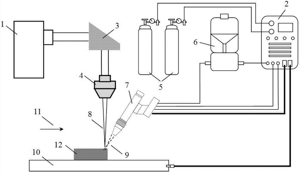
[0028] The substrate used in this example is a 304 stainless steel plate with a thickness of 4mm, and the powder material is austenitic stainless steel powder with a particle size of 200-300 mesh. The tungsten pole used is a cerium tungsten electrode, and the electrode connection method is that the cathode of the tungsten pole is connected to the negative pole of the power supply, and the substrate is connected to the positive pole of the power supply by the anode. The main arc current of the micro-beam plasma arc is 35A, the pulse laser peak power is 5.5kW, the pulse width is 5ms, and the defocus is 4mm. Adjust the laser emitting head 4 so that the angle between the laser beam and the vertical plane is 5°, and set the forward speed of the workbench to 12mm / s. The protective gas and working gas used in the micro-beam plasma arc and laser are both pure argon, and the flow rate of the protective gas is 15L / min, and the powder feeding rate of the powder feeder 6 is 20g / min. Cali...

Embodiment 2

[0030] The substrate used in this example is a 6061 aluminum alloy plate with a thickness of 4mm, and the powder material is AlSi-based aluminum alloy powder with a particle size of 200-300 mesh. The tungsten pole used is a cerium tungsten electrode, and the electrode connection method is that the cathode of the tungsten pole is connected to the negative pole of the power supply, and the substrate is connected to the positive pole of the power supply by the anode. The main arc current of the micro-beam plasma arc is 40A, the pulse laser peak power is 5.5kW, the pulse width is 4.5ms, and the defocus is 4.5mm. The angle between the laser beam and the vertical plane is 5°, and the exit direction of the micro-beam plasma arc is at an angle of 25° with the laser beam. Set the table forward speed to 10mm / s. The protective gas and working gas used in the micro-beam plasma arc and laser are all pure argon, and the protective gas flow rate is 20L / min, and the powder feeding rate is 15...


PUM

PropertyMeasurementUnit
thicknessaaaaaaaaaa
particle sizeaaaaaaaaaa
Defocus amountaaaaaaaaaa

Abstract

The invention discloses a laser three-dimensional rapid prototyping manufacturing method based on micro-arc powder loading. The method uses a micro-beam plasma arc to realize current-carrying and synchronous powder feeding of the powder, and uses a pulsed laser heat source to provide the main energy required for metal structure forming. . Use the excellent arc stability and straightness of the micro-beam plasma arc to improve the powder feeding accuracy of the powder material, use the energy concentration of the micro-beam plasma arc to improve the melting rate and deposition rate of the powder, and improve the powder material and forming area Thermal absorption rate of laser heat source energy. The main arc current of the micro-beam plasma arc is 30A-50A, and the pulse peak power of the pulsed laser beam is 4kW-10kW. and the output energy of the laser beam to realize the three-dimensional rapid prototyping of metal materials and structures, which has the advantages of high forming efficiency, high precision, small deformation, and strong technical adaptability.

Description

technical field [0001] The invention relates to a laser three-dimensional rapid prototyping manufacturing method, which is suitable for realizing laser three-dimensional rapid prototyping and manufacturing of metal materials such as stainless steel, aluminum alloy and titanium alloy in the form of synchronous powder feeding. Background technique [0002] Three-dimensional rapid prototyping manufacturing (3D printing) technology is an advanced manufacturing technology integrated with information technology, new material technology and manufacturing technology. The leading technology for the development of individualized manufacturing models. After just over 20 years, this technology has achieved rapid development, and has broad application prospects in many fields such as aerospace, micro-nano manufacturing, and biomedical engineering. The technical basis of 3D rapid prototyping of metal components is welding / connection. In the past 20 years, two major breakthroughs have bee...

Claims


Application Information

Patent Timeline
Patent Type & Authority Patents(China)
IPC IPC(8): B22F3/105B33Y10/00
CPCB33Y10/00B22F10/00B22F10/32B22F12/43B22F10/25B22F10/36B22F10/31B22F12/44B22F12/53Y02P10/25
Inventor 罗怡韩静韬谢小健朱亮陈东郭继钊李正
Owner CHONGQING UNIV OF TECH
Features
  • R&D
  • Intellectual Property
  • Life Sciences
  • Materials
  • Tech Scout
  • Unparalleled Data Quality
  • Higher Quality Content
  • 60% Fewer Hallucinations
Learn More