Iron nitride materials and magnets including iron nitride materials
A technology of nitrides and raw materials, applied in the direction of magnetism of inorganic materials, magnetic objects, magnetic materials, etc., can solve the problems of expensive permanent magnet manufacturing, high magnet manufacturing cost, environmental degradation, etc.
- Summary
- Abstract
- Description
- Claims
- Application Information
AI Technical Summary
Problems solved by technology
Method used
Image
Examples
Embodiment 1
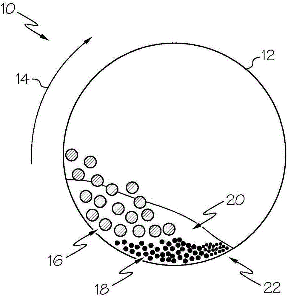
[0264] Figure 20 An example XRD spectrum is shown for a sample prepared from first grinding an iron precursor material to form a ferrous starting material, followed by grinding the ferrous starting material in a formamide solution. During milling of the iron precursor material, the ball milling apparatus was filled with a gas comprising 90% nitrogen and 10% hydrogen. Grinding balls having a diameter of about 5 mm to about 20 mm were used for grinding, and the mass ratio of balls to powder was about 20:1. During grinding of ferrous raw materials, the ball milling device is filled with formamide solution. Grinding balls having a diameter of about 5 mm to about 20 mm were used for grinding, and the mass ratio of balls to powder was about 20:1. as in Figure 20 The upper XRD spectrum shown in , shows that after grinding the iron precursor material, an iron-containing raw material comprising Fe(200) and Fe(211) crystalline phases is formed. XRD spectra were compiled using a D5...
Embodiment 2
[0266] Figure 21 Example XRD spectra are shown for samples prepared from grinding iron-containing raw materials in acetamide solution. During grinding of the iron precursor material, the ball mill unit was filled with a gas comprising 90% nitrogen and 10% hydrogen. Grinding balls having a diameter of about 5 mm to about 20 mm were used for grinding, and the mass ratio of balls to powder was about 20:1. During grinding of ferrous raw materials, the ball milling apparatus is filled with acetamide solution. Grinding balls having a diameter of about 5 mm to about 20 mm were used for grinding, and the mass ratio of the balls to powder was about 20:1. XRD spectra were compiled using a D5005 x-ray diffractometer available from Siemens USA, Washington D.C. as in Figure 21 As shown in the XRD spectra shown in , powders of iron nitrides are formed after grinding the iron-containing raw materials in acetamide solution. Powders containing iron nitrides including Fe 16 N 2 (002), ...
Embodiment 3
[0268] Figure 22 It is for Fe containing iron prepared by continuous casting, chilling and extrusion 16 N 2 A plot of the magnetization of an example magnetic material versus an applied magnetic field. First, an iron nitride mixture comprising an iron to nitrogen atomic ratio of about 9:1 is formed by grinding iron powder in the presence of amides. The average iron particle size was about 50nm ± 5nm as measured using scanning electron microscopy. Milling was carried out in the mixture using a nickel catalyst at a temperature of about 45° C. for about 50 hours. The weight ratio of nickel to iron is about 1:5. The atomic ratio of iron to nitrogen was measured using Auger Electron Spectroscopy (AES).
[0269] The iron nitride powder was then placed in a glass tube and heated using a torch. The torch uses a mixture of natural gas and oxygen as fuel and is heated at a temperature of about 2300°C to melt the iron nitride powder. The glass tube was then laid flat and the molt...
PUM
| Property | Measurement | Unit |
|---|---|---|
| The average diameter | aaaaa | aaaaa |
| Density | aaaaa | aaaaa |
Abstract
Description
Claims
Application Information
 - R&D
- Intellectual Property
- Life Sciences
- Materials
- Tech Scout
- Unparalleled Data Quality
- Higher Quality Content
- 60% Fewer Hallucinations
Browse by: Latest US Patents, China's latest patents, Technical Efficacy Thesaurus, Application Domain, Technology Topic, Popular Technical Reports.
© 2025 PatSnap. All rights reserved.Legal|Privacy policy|Modern Slavery Act Transparency Statement|Sitemap|About US| Contact US: help@patsnap.com


