High-speed centrifugal spinning device for producing nanofiber yarn in one-step shaping and production method of nanofiber yarn

A technology of nanofibers and high-speed centrifugation, applied in the textile field, can solve the problems of limited application range of nanofibers, poor mechanical properties of nanofiber membranes, single product form, etc., achieve good industrial production prospects, improve spinning quality, and process repeatability Good results

Inactive Publication Date: 2016-08-24
JIANGNAN UNIV
View PDF10 Cites 23 Cited by
  • Summary
  • Abstract
  • Description
  • Claims
  • Application Information

AI Technical Summary

Problems solved by technology

However, most of the current electrospun products are nanofiber membranes, and their product forms are single, which makes the application range of nanofibers limited.
The randomly oriented structure and poor mechanical properties of nanofibrous membranes greatly limit its textile applications
Its inherent defects limit the commercial use of this method on a large scale: mainly due to the need to apply a high-voltage electric field during the preparation of nanofibers, especially multi-needle centrifugal electrospinning, the jets ejected from the Taylor cone will repel each other due to the same charge , it is easy to make the droplet at the tip of the needle unstable, causing the needle to be blocked or the droplet to drop, the prepared nanofibers have poor shape and diameter uniformity, and the production efficiency is low; the raw materials for preparing nanofibers are single and are limited to polymers, while ceramics and metal materials The nanofibers cannot be prepared by this method; the polymer needs a certain proportion of solvent to make the solution have conductivity, and the pollution generated in the process
In recent years, the processing methods have been continuously improved, such as air-jet yarn forming method, double-electrode orientation yarn forming method, eddy current yarn forming method, wet method and collector rotation method, etc. Some of these devices cannot control the electric field repulsion between nozzles. effect, the spinning liquid jet direction is unstable, resulting in low fiber orientation and poor mechanical properties in the prepared nanofiber bundles
At the same time, some improved devices can improve the orientation of the prepared nanofiber bundles, but the device structure is complex, the number of spinnerets and other structural changes are inflexible, and the fiber bundle structure is single, which also limits the promotion of the device.

Method used


Image

  • High-speed centrifugal spinning device for producing nanofiber yarn in one-step shaping and production method of nanofiber yarn
  • High-speed centrifugal spinning device for producing nanofiber yarn in one-step shaping and production method of nanofiber yarn

Examples


Embodiment 1

[0031] Embodiment 1: the preparation of PLA nanofiber yarn

[0032] a, the preparation of PLA mass fraction is 5% CHCl 3 The solution was fully dissolved after magnetic stirring and ultrasonication.

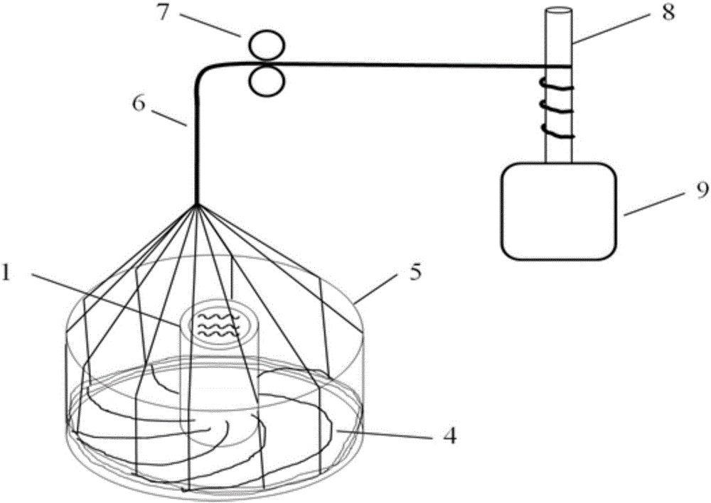
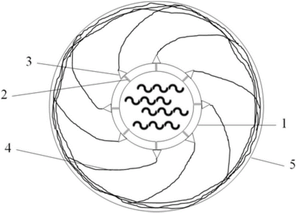
[0033] b, the CHCl that will be obtained 3 The solution is injected into the rotating centrifugal column 1, and the rotating centrifugal column 1, the radial channel 2, and the nozzle 3 are a linkage device, and rotate with the rotating centrifugal column 1 at a high speed, and the radial channel 2 supplies liquid to multiple nozzles 3 continuously.

[0034] c. Under the action of high-speed rotating centrifugal force, CHCl 3 The solution is sprayed out of nozzle 3, during which CHCl 3 The solvent is volatilized, and a plurality of PLA nanofibers 4 are obtained and rotated onto a cylindrical collector 5 . The diameter of the nanofiber can be regulated by controlling the rotational speed of the rotating spin column 1 .

[0035] d, a plurality of single PLA nanofibers 4 on the...

Embodiment 2

[0037] Embodiment 2: the preparation of nylon nanofiber yarn

[0038] a. Prepare a formic acid solution with a nylon mass fraction of 8-12%, and fully dissolve it after magnetic stirring and ultrasonication.

[0039] b. Inject the obtained formic acid solution into the rotating centrifugal column 1, the rotating centrifugal column 1, the radial channel 2, and the nozzle 3 are linkage devices, and rotate at a high speed with the rotating centrifugal column 1, and the radial channel 2 continuously supplies liquid to multiple nozzles 3 .

[0040] c. Under the action of high-speed rotating centrifugal force, the formic acid solution is sprayed out of the nozzle 3, and the formic acid solvent is volatilized during this process, and a plurality of nylon nanofibers are obtained and rotated to the cylindrical collector 5. The diameter of the nanofiber can be regulated by controlling the rotational speed of the rotating spin column 1 .

[0041] d. A plurality of single nylon nanofibe...

Embodiment 3

[0043] Embodiment 3: Preparation of PAN nanofiber yarn

[0044] a. Prepare a DMF solution with a mass fraction of PAN of 5-10%, and fully dissolve it after magnetic stirring and ultrasonication.

[0045]b. Inject the obtained DMF solution into the rotating centrifugal column 1, the rotating centrifugal column 1, the radial channel 2, and the nozzle 3 are linkage devices, and rotate with the rotating centrifugal column 1 at a high speed, and the radial channel 2 continuously supplies liquid to multiple nozzles 3 .

[0046] c. Under the action of high-speed rotating centrifugal force, the DMF solution is sprayed out of the nozzle 3. During this process, the DMF solvent is volatilized, and multiple PAN nanofibers are obtained and rotated to the cylindrical collector 5. The diameter of the nanofiber can be regulated by controlling the rotational speed of the rotating spin column 1 .

[0047] d, a plurality of single PAN nanofibers on the rotating spin column 1 are rotated at a c...


PUM

PropertyMeasurementUnit
thicknessaaaaaaaaaa

Abstract

The invention discloses a high-speed centrifugal spinning device for producing nanofiber yarn. The high-speed centrifugal spinning device is characterized by comprising a hollow rotating centrifugal column, a rotating cylinder collector, a roller, a winding unit and a transmission gear; a plurality of spray nozzles are arranged in the outer wall of the rotating centrifugal column, and the spray nozzles are communicated with a central cavity of the rotating centrifugal column through radial channels in the rotating centrifugal column; the rotating cylinder collector is located on the outer periphery of the rotating centrifugal column; the roller is located on the upper side of the rotating cylinder collector; the winding unit is located at the rear end of the roller, and the transmission gear drives the winding unit to rotate. The invention further discloses a production method of the nanofiber yarn. According to the advantages of the high-speed centrifugal spinning device in producing the nanofiber yarn, and spinning of the collector is combined technically, the nanofiber yarn which is controllable and highly oriented is obtained; the yield is greatly increased as compared with that of the nanofiber yarn obtained by other production methods, spinning quality is greatly improved, mechanical property of the nanofiber yarn is enhanced, machining reproducibility is good, and good industrial production prospect is achieved.

Description

technical field [0001] The invention belongs to the technical field of textiles, and in particular relates to a high-speed centrifugal spinning device for preparing nanofiber yarn by one-step forming and a preparation method for nanofiber yarn. Background technique [0002] Due to the unique advantages that other fibers cannot possess such as super large specific surface area, ultra-fine porosity and good physical and chemical properties, nanofibers are favored by experts and scholars, and their wide range of applications has attracted public attention, mainly for tissue engineering. Stents, drug release, filter media, artificial blood vessels, biochips, nanosensors, optics, energy storage, composite materials and other fields. There are many methods to prepare nanofibers, such as stretching method, microphase separation, template synthesis, self-assembly, electrospinning, etc. Among them, the electrospinning method can directly prepare continuous fibers from polymers or co...

Claims


Application Information

Patent Timeline
Patent Type & Authority Applications(China)
IPC IPC(8): D01D5/18D01D13/00D02G3/02D01F6/62D01F6/60D01F6/18
CPCD01D5/18D01D13/00D01F6/18D01F6/60D01F6/625D02G3/02
Inventor 魏取福吕鹏飞李大伟李国辉王清清黄锋林蔡以兵乔辉
Owner JIANGNAN UNIV
Why Eureka
Try Eureka