Manufacturing method for oil pump rotor
A technology of oil pump rotor and manufacturing method, which is applied in the direction of pump components, mechanical equipment, machines/engines, etc., and can solve the problem of affecting the service life of the internal and external rotor matching clearance of the oil pump, affecting product consistency and precision, and being unable to apply high-end oil pumps, etc. problem, to achieve the effect of improving assembly efficiency, improving precision, and good compression performance
- Summary
- Abstract
- Description
- Claims
- Application Information
AI Technical Summary
Problems solved by technology
Method used
Image

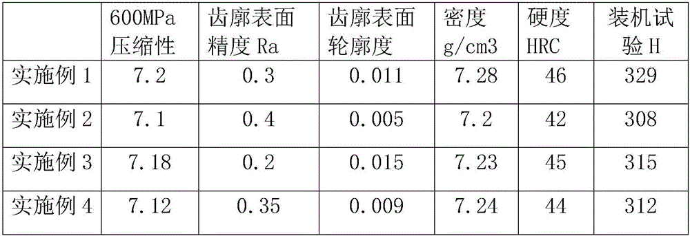
Examples
Embodiment
[0024] A method for manufacturing a high-density cycloidal rotor, comprising the following steps:
[0025] (1) Mixing: Weigh raw materials by weight percentage, 0-3.5% copper powder, 0.5-1.1% graphite, 0.05-0.10% spindle oil, 0.4-1.1% zinc stearate, and the balance is iron-based Alloy powder; put into a mixer and mix evenly, then take out to obtain mixed powder; the iron-based alloy powder contains 1.0-2.0% nickel, 0.4-1.2% molybdenum, and the rest is iron;
[0026] (2) Press the compact: Install the rotor pressing mold on the press, fill the mold cavity with mixed powder, press the inner and outer rotor compacts, and the compact density is 7.05-7.15g / cm 3 ;
[0027] (3) Pre-burning: place the compacted compact in a protective atmosphere, and pre-fire it at a temperature of 650-800°C for 30-50 minutes to form a pre-burned blank;
[0028] (4) Recompression: Install the rotor recompression mold on the press, put the pre-burned blank into the mold cavity, repress the pre-burned...
PUM
| Property | Measurement | Unit |
|---|---|---|
| density | aaaaa | aaaaa |
| density | aaaaa | aaaaa |
| density | aaaaa | aaaaa |
Abstract
Description
Claims
Application Information