Stamping backplane of a micro-arc reflector

A reflector and backplane technology, which is applied in the field of solar energy utilization, can solve the problems of unfavorable reflective surface strength and accuracy assurance, difficult reflective mirror surface shape accuracy, and heavy weight, so as to prevent the relative concentration of deformation in distribution and many processing procedures , to ensure the overall effect

Active Publication Date: 2019-05-14
DONGFANG BOILER GROUP OF DONGFANG ELECTRIC CORP
View PDF11 Cites 0 Cited by
  • Summary
  • Abstract
  • Description
  • Claims
  • Application Information

AI Technical Summary

Problems solved by technology

[0005] In the existing mirror (sub-mirror or facet) support method, the bracket welded by metal profiles is heavy, the overall strength of the structure is not high, and the shape accuracy and consistency of the joint surface with the mirror are difficult to guarantee; The small surface of the heliostat using the known stamped metal structure improves the defects of the welding structure of metal profiles in terms of forming accuracy and manufacturing efficiency, but it belongs to the standard flat joint surface, which has a great impact on the optical properties of the sub-mirror and the entire heliostat. No improvement in reflection performance
[0006] In the prior art, there are usually two ways to connect and fix the reflective surface of the heliostat and the support: one is to directly fix the reflector on the support of the heliostat, which is realized by setting support points at the corresponding positions of the support. The size of the mirror truss structure is large, and the positioning references of each support point cannot be completely consistent during processing. As a result, for the same mirror, several fulcrums on it cannot form an ideal surface shape, and are also affected by the truss structure. impact, the distribution of support points cannot be ideal, so this method is not conducive to the strength and accuracy of the reflective surface; another common structure is to add a first-level metal frame between the heliostat bracket and the reflective surface. The form of the frame is composed of hashed or welded frame metal profiles. Among them, the hashed support has no advantage in stabilizing the surface shape of the reflector, and the on-site installation accuracy is high; and the welded frame structure is relatively difficult due to its processing method. The large amount of deformation makes it difficult to achieve higher mirror surface accuracy and design the ideal surface structure, and this structure also brings relatively large amount of materials, heavy structure, and low production efficiency of the frame itself. Conducive to large-scale assembly line production and other disadvantages

Method used


Image

  • Stamping backplane of a micro-arc reflector
  • Stamping backplane of a micro-arc reflector
  • Stamping backplane of a micro-arc reflector

Examples


Embodiment 1

[0048] Taking the heliostat in the tower-type solar thermal power generation technology as an example, combined with the current mainstream rectangular heliostat mirror (or facet) shape, in order to make the technical solution and advantages of the present invention more clear, the following is combined with illustrations and implementation For example, the present invention is described in detail.

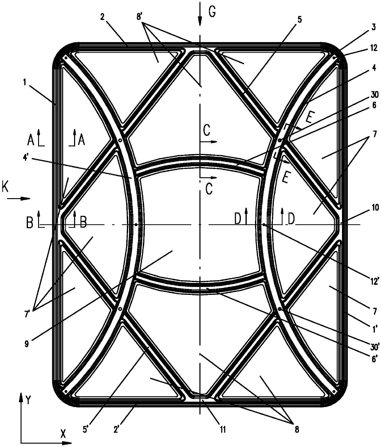
[0049] Such as figure 1 As shown, a micro-arc mirror stamping back plate, the back plate is punched and formed by cutting thin steel plate (stretched plate), on the overall frame structure of the back plate, each forming part inside the back plate Four inward inclined surfaces 7, 7', 8, 8' are formed, so that when the reflector body is bonded and fixed to the back plate, the spatial shape of the back plate forces the reflector to sag toward its center point, A slight elastic deformation is produced, so that the surface shape of the reflector produces a slight arc, and a certain d...

Embodiment 2

[0057] This embodiment is basically the same as Embodiment 1, the difference is that: when the ring-shaped forming part is a circular structure, it is preferable to refer to the actual arrangement of the arc-shaped forming part, the connecting arm and the reinforcing arm. Figure 9 As shown: the reinforcement arms 5, 5' are sequentially connected to four points evenly distributed on the circular ring-shaped forming part 1, forming a square; the arc-shaped forming parts 4, 4' are connected to the corresponding two adjacent reinforcement arms The arc midpoint on the ring-shaped forming part, the two arc-shaped forming parts 4, 4' are left and right symmetrical and symmetrical to the center of the circle; the connecting arms 6, 6' connect the two 1 / 4 positions on the two arc-shaped forming parts, The two connecting arms are symmetrical up and down and centered on the center of the circle.

Embodiment 3

[0059] This embodiment is basically the same as Embodiment 1, the difference is: when the ring-shaped forming part is an elliptical structure, the actual layout rules of the preferred arc-shaped forming part, connecting arm and reinforcing arm are referred to in reference Figure 10 As shown: the reinforcement arms 5, 5' are sequentially connected to four points evenly distributed on the elliptical ring-shaped forming part, that is, the intersection of the long and short axes and the ellipse, forming a rhombus; two arc-shaped forming parts 4, 4' The left and right symmetry and the center of the circle are symmetrical; the two connecting arms 6, 6' are symmetrical up and down and are symmetrical about the center of the circle.


PUM


Abstract

The invention discloses a punched back plate of a micro-arc surface reflector, which belongs to the field of back support of solar concentrator reflectors, and comprises a ring-shaped forming part along the edge of the reflector, which is distributed on the left and right sides of the ring-shaped forming part. Two arc-shaped molding parts that are left-right symmetrical and protrude inward, two sets of upper and lower symmetrical arc-shaped connecting arms connecting the central areas of the two arc-shaped molding parts, and at least four evenly distributed circumferentially connecting ring-shaped molding parts. point and intersect with the arc-shaped forming part to form or intersect to form a rhombus or regular polygonal reinforcing arm; the ring-shaped forming part forms a plane structure, and the arc-shaped forming part, connecting arm and reinforcing arm form a plane structure opposite to the plane. Slightly curved surface concave towards its central region. The invention improves the surface shape accuracy and reflection light spot quality of the reflective surface of the heliostat, improves the manufacturing efficiency and the consistency of component sizes of the supporting structural parts of the reflective mirror, and reduces the manufacturing cost of the structural parts of the heliostat.

Description

technical field [0001] The invention belongs to the field of solar energy utilization, and more specifically relates to a tower-type solar thermal power generation system, which can be used as a back plate of a reflector of a heliostat or a back support of a reflector of a concentrator with a similar principle. Background technique [0002] Tower solar thermal power generation is one of the main forms of solar thermal power generation. The basic principle is: use the mirror field composed of many heliostats to gather sunlight to the heat collector at a fixed position through one or more reflections, heat the working medium in the heat collector, and then the working medium is transported, stored Heat, heat exchange with water and other links, generate superheated steam to drive the turbine generator to generate electricity. [0003] The function of the mirror field in the tower-type photothermal power station is to gather light and heat. It is composed of several heliostats...

Claims


Application Information

Patent Timeline
Patent Type & Authority Patents(China)
IPC IPC(8): G02B7/183F24S23/70
CPCG02B7/183Y02E10/40
Inventor 华文瀚蒋超猛奚正稳孙登科王娟娟张平
Owner DONGFANG BOILER GROUP OF DONGFANG ELECTRIC CORP
Why Eureka
Try Eureka