

Water treatment method and water treatment apparatus each using membrane
A water treatment device and water treatment technology, applied in water/sewage treatment, water treatment parameter control, biological water/sewage treatment, etc., can solve problems such as inability to remove chemical attachments, achieve energy saving, improve cleaning effect, The effect of reducing the aeration air volume
- Summary
- Abstract
- Description
- Claims
- Application Information
AI Technical Summary
Problems solved by technology
Method used
Image

Examples
Embodiment approach 1
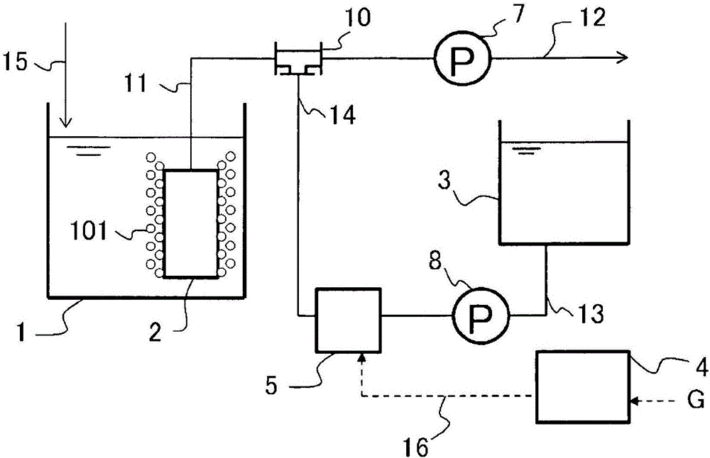
[0065] figure 1 It is a block diagram showing Embodiment 1 of the present invention. In the configuration of the present embodiment, the membrane filtration separation device 2 is immersed in the water tank 1 to be treated, and is connected to the switching valve 10 through the membrane connection pipe 11 . The switching valve 10 is branched into a filtered water piping 12 and an ozone water piping 14 , the filtered water piping 12 is connected to the switching valve 10 , and the filtering pump 7 is located on the piping path of the filtered water piping 12 . Moreover, the ozone mixing tank 5 which is an ozone dissolving part is connected to the ozone water piping 14. As shown in FIG. A washing water tank 3 is connected to the upstream side of the ozone mixing tank 5 through a washing water pipe 13 , and a washing water supply pump 8 is located on the washing water pipe 13 between the ozone mixing tank 5 and the washing water tank 3 . And the ozone generator 4 which is an oz...
Embodiment approach 2
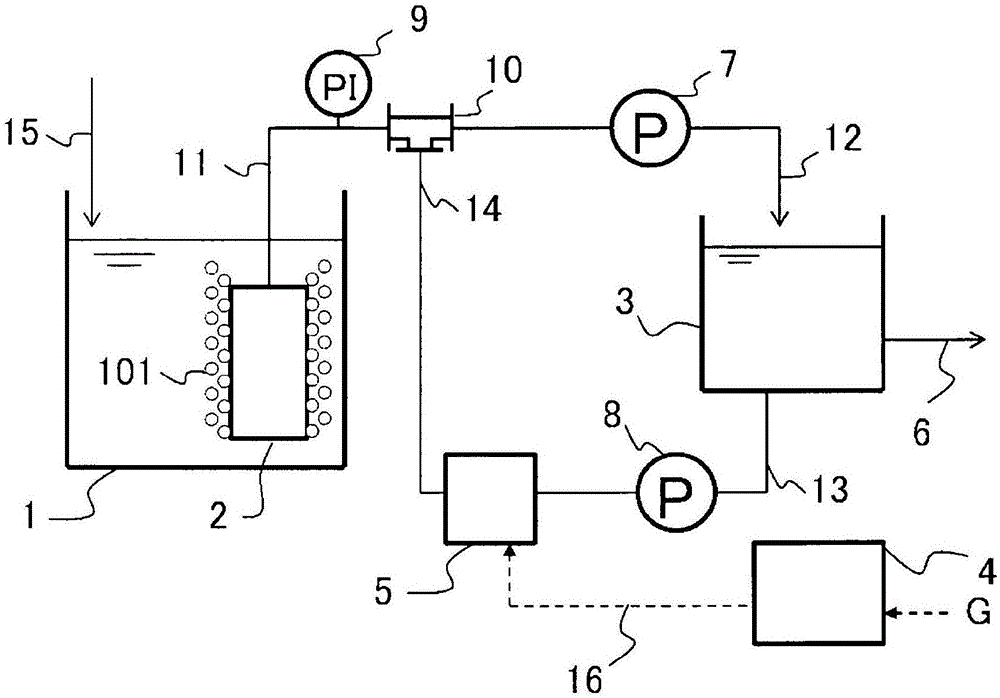
[0109] Figure 8 It is a block diagram showing an example of Embodiment 2 of the present invention. right image 3 The following structures are added. An ozone gas storage tank 17 capable of storing ozone gas is provided between the ozone generator 4 and the ozone mixing tank 5 through the ozone gas piping 16 . Furthermore, the ozone gas storage tank 17 and the ozone generator 4 are connected via an oxygen pipe 18 .
[0110] Next, the operation will be described. During backwashing, the ozone gas produced by the ozone generator 4 using oxygen as a raw material is transported to the ozone gas storage tank 17 through the ozone gas pipeline 16, and is stored in the ozone gas storage tank 17 by being adsorbed on an adsorbent such as silica gel at a low temperature. As indicated by symbol G in the drawing, oxygen-containing gas is supplied to the ozone generator 4, and in this example, it is more preferable to supply oxygen gas generated from liquid oxygen than to supply oxygen...
Embodiment approach 3
[0131] Figure 12 It is a block diagram showing an example of Embodiment 3 of the present invention. right image 3 The following structures are added. The acid storage tank 19 is connected to the ozone water pipe 14 through an acid supply pipe 21 . Furthermore, an acid supply pump 20 is provided on an acid supply pipe 21 between the acid storage tank 19 and the ozone water pipe 14 .
[0132] Next, the operation will be described. During backwashing, when the ozone cleaning water is supplied to the membrane filtration separation device 2, the acid in the acid storage tank 19 is supplied to the ozone cleaning water in the ozone water piping 14 through the acid supply piping 21 by the acid supply pump 20 at the same time to generate acidic water. Ozone cleans the water, and backwashes the membrane filtration separation device 2. It is also possible to install a static mixer or the like at a position downstream of the point where the acid is injected into the ozone water pip...
PUM
 Abstract
Description
Claims
Application Information